Tube Fitting Feeding Guide 2026
Tube fittings bring mixed geometry into a very small part envelope
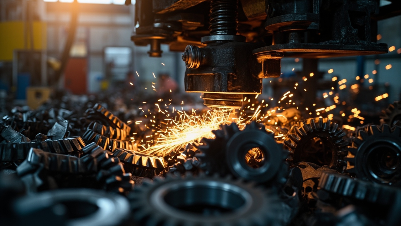
Tube fittings look compact, but they often combine threads, wrench flats, elbows, sealing faces, and short overall length in one small part. That creates a feeding problem where several surfaces matter at once and the wrong contact point can damage the part or confuse orientation.
The feeder concept has to respect both part geometry and the next assembly action. This article pairs well with our nut feeding guide and sensor selection guide.
Why small fittings are tougher than they look
The first issue is mixed geometry. A fitting may have one end threaded, another end shaped for a tube, and a body that wants to rotate differently depending on where the track contacts it.
The second issue is surface protection. Threads, sealing faces, and plated areas do not all tolerate the same level of contact or impact.
The third issue is station demand. A screw-in station, torque station, or robot pick usually wants one very specific release pose, so “one part at a time” is not enough.
| Case | Main risk | Design focus | What to verify |
|---|---|---|---|
| Straight threaded fitting | Thread damage | Body-based guidance | Thread condition after run |
| Elbow fitting | Orientation drift | Use the body shape deliberately | Final rotational pose |
| Plated pneumatic connector | Surface marks | Protected contact path | Cosmetic quality |
| Mixed fitting family | Long changeover | Modular tooling | Reset time by variant |
Choosing a feeder concept for tube fittings
For one fitting family at stable volume, a dedicated bowl feeder is usually the practical answer. It keeps the layout compact and lets the geometry do the orientation work, provided the contact path is chosen carefully.
For several fitting types, modular change parts or a flexible presentation stage may save more time than trying to squeeze every variant through one fixed bowl concept. Small fittings have a way of punishing universal tooling.
Final release design matters a lot here. Even a good bowl can be undermined if the last stop, escapement, or nest lets the fitting twist before the station takes it.
Rules that reduce fitting-feeder problems
- Choose safe contact surfaces first. Threads and seal faces should not become tooling references if avoidable.
- Define the required final pose clearly. That should drive the selector logic.
- Review variant spread honestly. A broad fitting family may not belong in one fixed setup.
- Validate at the real station. Torque and pick interfaces expose weak presentation margins fast.
Small fittings often reward simpler, more deliberate tooling. Most trouble starts when the design touches a surface that the assembly process cares about.
How to validate tube-fitting feeders
Inspect thread condition and usable station presentation separately. One feeder can score well on rate and still damage the surface that matters most.
Run with the actual fitting finish and oil state. Dry sample parts tend to hide the friction and slip problems that show up later.
If the line includes torqueing or screw-in assembly, validate the release pose and dwell stability at the point where the tool engages the part.
Buyer checklist before requesting a quote
- Send the exact fitting family and finish condition.
- State which surfaces cannot be damaged.
- Describe the required final pose at the next station.
- Include variant count and changeover expectation. This affects whether a dedicated or modular concept makes sense.
Huben Automation reviews fitting-feeding projects around geometry-driven orientation, surface protection, and station-ready release. If you want help checking a tube-fitting application, send us the samples and assembly details.
Ready to Automate Your Production?
Get a free consultation and detailed quote within 12 hours from our engineering team.


