Tube and Pipe End Feeding: Automated Handling for CNC Machining Lines 2026
Tubes and pipes are cylindrical, but feeding them is rarely straightforward
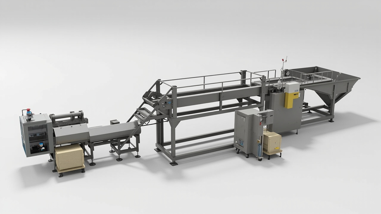
Tube and pipe end feeding systems serve CNC machining, threading, grooving, and end-forming operations where the part must arrive at the tool with a known orientation and one end presented to the chuck, collet, or fixture. On paper, a cylindrical part looks simple. In practice, tubes, pipes, and short cut sections create a feeding challenge that depends heavily on the length-to-diameter ratio, wall thickness, and whether the open ends invite nesting or tumbling in bulk.
The feeder concept for tube and pipe parts must address three competing needs: prevent interlocking, protect the end that goes into the tool, and deliver a consistent presentation pose at the required rate. This article covers the geometry-driven decisions, tooling strategies, and integration details that engineering teams need when specifying a tube end feeding system for production.
This guide connects with our broader coverage of bushing and sleeve feeding, pin feeding systems, and bowl feeder design for assembly machines.
Length-to-diameter ratio: the geometry that drives everything
The single most important number in tube feeding is the length-to-diameter ratio, or L/D ratio. It determines whether the part will stand, roll, tumble, or nest when placed in bulk motion.
Short stubby parts with an L/D ratio below about 1.5 tend to roll freely and present multiple stable poses. These parts often need track features that deliberately create a preferred orientation, such as a step or a narrow slot that forces the part to stand on one end.
Medium-length tubes with an L/D ratio between 1.5 and 4 are the hardest category. They are long enough to tilt and bridge across track features, but short enough that they still tumble and flip. These parts typically need progressive orientation tooling that first lifts one end, then guides the part into a single pose over several centimeters of track.
Long tubes with an L/D ratio above 4 tend to lie flat or stand on end depending on the surface they land on. They are generally easier to orient once they commit to one direction, but their length creates handling and space constraints in the feeder layout.
| Tube type | Typical L/D ratio | Outer diameter (mm) | Feed challenge | Recommended track approach | Expected feed rate (ppm) |
|---|---|---|---|---|---|
| Short cut sleeve | 0.8 - 1.5 | 6 - 25 | Rolling, multiple stable poses | Narrow track with end-up step | 60 - 180 |
| Medium pipe section | 1.5 - 4.0 | 8 - 40 | Bridging, tilting, tumbling | Progressive orientation, side rail | 30 - 100 |
| Long tube blank | 4.0 - 12.0 | 10 - 60 | Space constraint, end damage | Gentle incline, end-guided track | 15 - 60 |
| Thin-wall hose nipple | 2.0 - 6.0 | 4 - 12 | Deformation, nesting | Soft contact, anti-nest baffle | 40 - 120 |
| Brass fitting blank | 1.0 - 3.0 | 12 - 30 | Heavy, end protection | Hard track with protected end zone | 25 - 80 |
Preventing nesting and tumbling in the bowl
Nesting is the most common failure mode in tube and pipe feeding. When two tube ends meet, one tube can slide partially or fully inside the other. Once nested, the pair moves through the track as a single unit and creates a misfeed at the release point. The risk increases with thin-wall tubes, wide-open bore diameters, and high bowl fill levels.
Anti-nesting design starts in the bowl itself. Stepped or tapered bowl floors encourage parts to stand on one end before entering the track. A central cone or spiral ramp that is slightly narrower than the tube bore prevents nested pairs from forming at the pickup point.
Secondary nesting prevention happens on the track. A slot or gap that is wider than the tube wall but narrower than the full bore depth allows the open end to hang through. If a second tube tries to enter the same space, it is blocked by the track geometry and recirculated. This is a passive, reliable method that does not depend on sensors or controllers.
Tumbling refers to parts that flip between horizontal and vertical poses mid-track. Progressive guide rails that gradually narrow the allowable clearance reduce tumbling by eliminating the space that allows the flip. The key is gradual reduction. A sudden constriction creates a jam point rather than an orientation gate.
End protection and deburring before feeding
The end that goes into the CNC chuck or collet must arrive clean and undamaged. Burrs from the cutting operation create two problems. First, burrs catch on track surfaces and selectors, increasing jam frequency. Second, burrs transfer into the chuck, causing poor gripping force and part slippage during machining.
In high-volume lines, a dedicated deburring station before the feeder is the most reliable approach. Vibratory deburring bowls with abrasive media can remove cutting burrs in a separate upstream step. The cleaned part then enters the orientation feeder with a clean end.
When deburring is not available upstream, the feeder track must tolerate the as-cut condition. This means wider clearances, softer contact surfaces, and more recirculation capacity to handle the parts that get caught on burrs.
End caps and protective plugs used during storage and transport must also be handled separately. If the line feeds parts with caps still in place, a cap-removal station with its own cap and lid feeding system should precede the tube feeder. Feeding the cap separately to a capping station downstream closes the loop.
Bowl feeder versus flexible feeding for tube parts
For tube and pipe families with stable geometry and long production runs, a dedicated vibratory bowl feeder remains the cost-effective choice. The orientation tooling is cut once and runs at high speed for weeks between changeovers. Huben's standard bowl systems cover the full range from small 6 mm nipples to 60 mm pipe blanks, with feed rates from 15 to 180 ppm depending on part size.
Flexible feeding becomes relevant when the product family includes multiple tube diameters, lengths, or materials, and the line changes between variants several times per shift. A vision-guided flexible feeder handles mixed geometries without physical tooling changes, trading raw speed for flexibility. Huben's flexible systems support tube parts from 4 to 80 mm with recipe-based changeovers under 15 minutes.
The decision criteria are the same as for any bowl versus tray feeding comparison: variant count, changeover frequency, and the tolerance for retooling time versus the need for maximum throughput.
Integration with CNC loading and end-forming stations
The feeder is only one part of the cell. The discharge design must match the CNC loading method. A collet-style CNC expects the tube end presented vertically, centered, and stationary. A chuck-style CNC may accept a horizontal approach, but the feeder still needs a controlled stop to prevent the part from rotating before the jaws close.
For end-forming operations like flaring, beading, or threading, the feeder typically delivers the part to a transfer point where a robot or pneumatic slide picks it and inserts it into the forming tool. The discharge nest must replicate the tool's grip geometry so that the transfer does not introduce angular error.
Sensor placement at the discharge point is critical. A part-presence sensor confirms that the nest is full before the robot picks. An orientation-verification sensor confirms that the correct end faces the tool. Without these checks, a mis-oriented part can damage the forming tool or the CNC chuck.
Lines that process both tube blanks and finished fittings benefit from shared quick-change tooling systems that allow the same feeder base to accept different orientation inserts for different part families.
HVAC and automotive: where tube feeding matters most
HVAC manufacturing uses large volumes of copper and aluminum tube sections for evaporator coils, condenser headers, and refrigerant lines. These parts are typically thin-wall, medium L/D ratio, and arrive from a tube-cutting saw in bulk. The feeder must handle the as-cut burr condition and present one clean end to the brazing or expanding tool.
Automotive fuel and brake lines use steel or stainless tubes that are cut, deburred, and fed to end-forming stations. The tolerances are tighter than HVAC, and the surface protection requirements are stricter. Scratches on the outer diameter or burrs on the inner diameter can cause leak-test failures downstream.
Both industries benefit from feeder designs that include recirculation paths for parts that fail orientation checks, rather than simply rejecting them. A recirculated part gets another chance to orient correctly without creating scrap or requiring operator intervention.
Design rules for tube and pipe feeding systems
- Start with the L/D ratio. It dictates the orientation strategy, the bowl floor shape, and the track profile.
- Design for nesting prevention before feed rate. A fast feeder that nests is worse than a slower feeder that runs clean.
- Know the burr condition. Test with as-cut parts, not hand-cleaned samples. If burrs are significant, plan for upstream deburring or wider track tolerances.
- Protect the tool-facing end. The end that enters the CNC or forming tool should have the smoothest contact path in the entire system.
- Validate discharge at real cycle time. The feeder may look perfect at the bowl, but the transfer to the CNC spindle is where most errors occur.
- Plan end cap handling separately. If parts arrive with caps or plugs, the removal and cap-feeding loop should be designed as a parallel subsystem.
Tube size and feeding parameter reference
| Application | Material | OD (mm) | Wall (mm) | Length (mm) | L/D | Feeding method | Typical rate (ppm) | Nesting risk |
|---|---|---|---|---|---|---|---|---|
| HVAC copper tube | Cu | 9.52 | 0.71 | 30 - 80 | 3.2 - 8.4 | Bowl, anti-nest track | 40 - 80 | High |
| Brake line tube | Steel | 4.76 | 0.70 | 15 - 40 | 3.1 - 8.4 | Bowl, progressive orient | 60 - 120 | Medium |
| Fuel rail nipple | Steel | 12.0 | 1.5 | 20 - 50 | 1.7 - 4.2 | Bowl, end-up step | 50 - 100 | Medium |
| AC compressor fitting | Al | 16.0 | 2.0 | 25 - 60 | 1.6 - 3.8 | Bowl, side-guided track | 30 - 70 | Low |
| Hydraulic hose barb | Brass | 8.0 | 1.2 | 12 - 30 | 1.5 - 3.8 | Bowl, narrow slot orient | 60 - 150 | High |
| Heat exchanger header | Steel | 25.0 | 1.5 | 40 - 100 | 1.6 - 4.0 | Bowl, spiral ramp | 20 - 50 | Medium |
Buyer checklist before requesting a quote
- Send actual production tube blanks. Length tolerance, wall thickness variation, and burr condition all affect feeding.
- Specify the L/D ratio and any nested-pair risk. This determines the bowl floor and anti-nesting design.
- State which end goes into the tool. The feeder must protect this end from contact and burr damage.
- Include deburring status. Whether parts arrive as-cut or pre-deburred changes the track tolerance design.
- Describe the CNC loading method. Collet, chuck, or robotic pick each require a different discharge nest geometry.
- Note variant count and changeover expectation. This determines whether a dedicated bowl or a flexible feeder is more suitable.
Huben Automation designs tube and pipe end feeding systems around L/D ratio analysis, nesting prevention, and CNC-compatible discharge presentation. If your team is evaluating a tube feeding application, send us the sample parts and CNC loading details for a feasibility review.
Frequently asked questions
How do I prevent tubes from nesting inside each other during feeding?
Nesting is prevented by a combination of bowl floor geometry and track design. A stepped or conical bowl floor encourages tubes to stand on one end rather than lie flat and overlap. On the track, a slot or gap that is narrower than the tube's inner diameter prevents a second tube from entering the open end. If nesting is severe, an upstream vibratory separator can spread parts before they enter the orientation bowl.
Should I deburr tubes before feeding or design the feeder to handle burrs?
The best practice is to deburr upstream if possible. A dedicated deburring bowl or tumbler removes cutting burrs before the parts reach the orientation feeder, resulting in cleaner feeding and fewer jams. If upstream deburring is not available, the feeder track must be designed with wider clearances and softer contact surfaces to tolerate as-cut burr conditions. Test always with production-condition parts, not hand-cleaned samples.
What is the ideal L/D ratio for bowl feeding, and what happens outside that range?
Tubes with an L/D ratio between 2 and 4 are the most challenging because they tend to tilt, bridge, and tumble. Short parts below 1.5 are easier to orient because they roll into a predictable position. Long parts above 4 are generally stable but require more feeder space. Parts with extreme L/D ratios may benefit from flexible feeding or a dedicated linear track rather than a full spiral bowl.
How should I handle end caps or protective plugs that arrive on the tubes?
End caps should be handled as a separate subsystem. A cap-removal station strips the cap before the tube enters the orientation feeder. The caps are then fed through their own cap and lid feeding system to the downstream capping operation. Trying to feed capped and uncapped tubes through the same track creates inconsistent orientation and frequent jams.
How do I protect the outer diameter of precision tubes during vibratory feeding?
Surface protection depends on the bowl and track material. For precision tubes that must remain scratch-free, nylon or coated bowl surfaces reduce impact marks. Teflon coating on the track reduces friction and part-to-part contact. The track profile should minimize sharp transitions and use radiused edges wherever the part changes direction. For the highest cosmetic standards, a flexible feeder with soft pick pads eliminates all vibratory contact.
Can one feeder handle multiple tube diameters and lengths on the same line?
A dedicated bowl feeder can handle multiple variants if the parts are close in size and the changeover uses modular tooling inserts. For widely different diameters or lengths, a flexible feeder with vision-guided pickup is the better choice. Huben's flexible systems support tube parts from 4 to 80 mm with recipe-based changeovers in under 15 minutes, compared to 30 to 60 minutes for a mechanical tooling swap on a bowl feeder.
Ready to Automate Your Production?
Get a free consultation and detailed quote within 12 hours from our engineering team.


