O-Ring and Seal Feeding Systems: Handling Deformed and Sticky Parts 2026
Why O-rings and seals are uniquely challenging in automated feeding
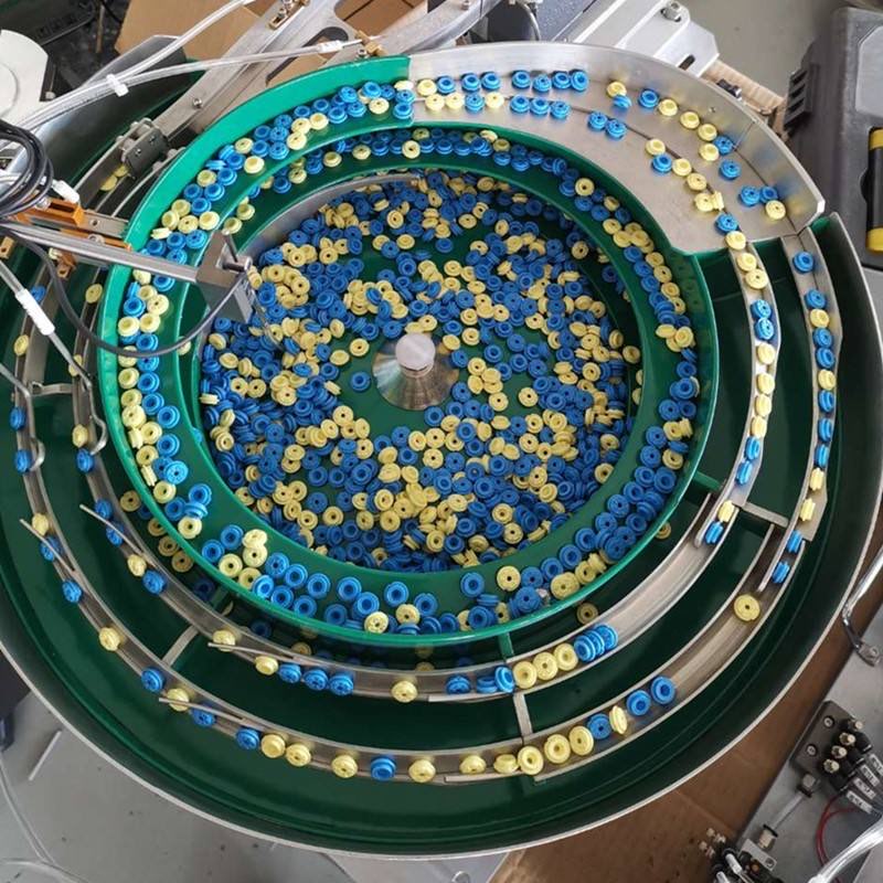
O-ring and seal feeding projects often look straightforward at the quotation stage. The part is small, round, and symmetric. On paper, it should be easy to feed. In reality, elastomer and rubber parts behave nothing like metal fasteners. They deform under load, cling to each other through static and surface tack, roll unpredictably on hard surfaces, and change behavior with oil content, powder coating, and ambient humidity. An O-ring feeding system that works perfectly during a supplier demonstration can become unreliable on the production floor within a single shift.
The core issue is that elastomer parts are soft, flexible, and adhesive. A metal screw maintains its shape regardless of vibration level. An O-ring flattens, stretches, and sticks. A rubber seal can fold onto itself, trap air, or latch onto a neighboring part. These behaviors make bulk handling, orientation, and discharge fundamentally different from rigid parts. Engineers who approach an O-ring feeding system the same way they approach a screw feeder usually discover the mistake after the tooling is already built.
This guide covers the specific challenges of handling O-rings, gaskets, and soft seals in vibratory bowl feeders and flexible feeding systems. We address deformation prevention, static control, material stickiness, clean room compatibility, and orientation strategies for medical device and automotive assembly lines. If your line already handles rubber components, our rubber parts feeding guide provides additional context on material-specific behavior. For clean room environments, the clean room feeding guide covers complementary requirements.
O-ring deformation: causes, consequences, and countermeasures
Deformation is the single most common cause of unreliable O-ring feeding. When O-rings are loaded in bulk into a vibratory bowl, the weight of the upper layers compresses the lower layers. Even a few hundred rings can generate enough pressure to temporarily change the cross-section of rings at the bottom. A flattened ring does not sit in a track pocket the way a round ring does. It rolls differently, presents inconsistently to the escapement, and may fail downstream inspection even though it would recover its shape if left undisturbed.
The severity of deformation depends on three factors: the durometer of the elastomer, the bulk fill height, and the dwell time at the bottom of the stack. Softer materials like silicone (40-50 Shore A) deform more easily than harder materials like fluorocarbon (70-80 Shore A). Higher fill levels create more compression. Longer dwell times allow the deformation to become more pronounced. A ring that sits compressed for ten minutes recovers more slowly than one that moves through the bowl in thirty seconds.
The most effective countermeasure is to limit the bulk fill height. Many O-ring feeding systems perform reliably when the bowl is kept at 30 to 50 percent capacity rather than being packed full. This requires a hopper and level control system that refills the bowl before it empties but does not overfill it. A photoelectric or ultrasonic sensor at the target fill level triggers the hopper to add a controlled batch of rings. This keeps the bulk pressure low and the deformation minimal.
For very soft O-rings that deform even at moderate fill levels, a flexible feeding system may be necessary. Flexible feeders present parts individually from a tray or pocket, eliminating bulk compression entirely. The trade-off is lower throughput and higher equipment cost. For high-volume lines, a custom nylon bowl with shallow pocket tracks often strikes the right balance between speed and gentle handling.
| Elastomer type | Typical durometer | Deformation sensitivity | Recommended bowl type | Max fill level |
|---|---|---|---|---|
| NBR (Nitrile) | 50-70 Shore A | Moderate | Nylon or PTFE-coated steel | 40-50% |
| Silicone | 40-60 Shore A | High | Shallow-pocket nylon bowl | 30-40% |
| EPDM | 50-75 Shore A | Moderate | Nylon or soft-coated steel | 40-50% |
| FKM (Fluorocarbon) | 65-85 Shore A | Low | PTFE-coated steel | 50-60% |
| Neoprene | 50-70 Shore A | Moderate | Nylon bowl | 40-50% |
Static electricity and its impact on O-ring feeding
Static charge is a silent problem in O-ring feeding systems. Dry, lightweight O-rings, especially silicone and FKM, generate significant static electricity when they rub against the bowl surface. Once charged, the rings attract each other and stick to the bowl walls. A charged O-ring may climb the side of the bowl instead of the track, bypass the tooling entirely, or travel in pairs that cause double-feeds at the discharge.
Static problems are worse in low-humidity environments. Many manufacturing facilities operate at 30 to 40 percent relative humidity in winter, which is precisely where static charge builds most aggressively. The problem may appear suddenly when the season changes, even though the feeder hardware has not changed at all. This is why static control should be part of the initial O-ring feeding system design, not an afterthought added when the line starts misfeeding.
The most reliable approach is a combination of conductive bowl materials and ionizing air. A conductive bowl surface, such as a carbon-filled nylon or a metal bowl with a dissipative coating, prevents charge buildup by providing a path to ground. Ionizing air nozzles positioned near the track entry neutralize charge on the parts as they begin to move. The ionizer should be sized for the track width and positioned where the parts are still in bulk, before they separate into single file.
Grounding is essential but often neglected. The bowl, the track, and the support structure should all be bonded to a common ground point. A floating ground or a broken ground wire can make static problems appear intermittent, which is harder to diagnose than a complete absence of grounding. During maintenance checks, verify ground continuity with a multimeter as part of the routine. More on static control strategies can be found in our ESD control guide.
Material stickiness and surface tack management
Many O-rings and seals are coated with a thin film of oil, powder, or mold release agent from the manufacturing process. This coating creates surface tack that causes rings to cling together. An O-ring that has stuck to another ring will not separate on a track unless there is a mechanism specifically designed to break the bond. Vibration alone is usually not enough, especially if the vibration amplitude is kept low to prevent deformation.
The type of coating matters. Silicone oil produces less tack than mineral oil. Talc powder reduces tack more effectively than oil but introduces contamination concerns in clean room environments. Some O-ring suppliers use no coating at all, delivering dry rings that are actually easier to separate because there is no adhesive film between them. When selecting an O-ring supplier for an automated line, the coating strategy should be part of the evaluation criteria.
For rings that arrive with a sticky coating, several countermeasures are available. A gentle brushing mechanism at the bowl entry can mechanically separate stuck pairs. A low-pressure air curtain can blow between rings as they climb the track, breaking weak adhesive bonds. For the most stubborn cases, a rotating brush wheel with soft bristles can knock apart clusters of rings before they enter the precision tooling section. The brush must be soft enough to avoid damaging the ring surface, which rules out most metal or stiff nylon brushes.
Temperature also affects stickiness. Many elastomer coatings become less tacky at slightly elevated temperatures. A small heater built into the bowl base can raise the surface temperature by 5 to 10 degrees Celsius, which is often enough to reduce tack without affecting the O-ring material properties. This approach is commonly used in automotive seal feeding lines where NBR rings arrive with a light oil film.
Clean room considerations for O-ring feeding in medical and semiconductor applications
Medical device and semiconductor assembly lines often require ISO Class 7 or Class 8 clean room environments. An O-ring feeding system in a clean room must meet particle generation limits that standard industrial feeders do not address. Every vibration event, every part-to-part contact, and every track surface generates some level of particulate. In a clean room, that particle count matters.
The first requirement is a sealed enclosure. The bowl and track should be enclosed in a transparent housing with gasketed seams. The enclosure prevents particles from escaping into the clean room and protects the parts from external contamination. A slight positive pressure of filtered air inside the enclosure helps keep particles from leaking out through any small gaps. The enclosure material should be easy to clean and resistant to common clean room disinfectants.
The second requirement is low-particle bowl surfaces. Nylon bowls generate more particles than coated metal bowls. For clean room applications, a stainless steel bowl with a PTFE or PFA coating is preferred because it produces minimal particles and can be wiped clean without degrading the surface. The coating must be food-grade or medical-grade and should not contain fillers that could flake off during vibration.
The third requirement is particle monitoring. A clean room feeding system should include a particle counter or at least a scheduled swab test program to verify that the feeder does not exceed the clean room particle limits. The monitoring frequency depends on the clean room class and the regulatory requirements of the application. For medical device lines under FDA oversight, this data is part of the equipment validation package.
If your application involves medical device assembly, you may also need to plan for IQ/OQ/PQ validation. Our IQ/OQ/PQ guide explains how to structure the validation protocol for feeding equipment in regulated environments. For gasket-specific challenges, the gasket feeding guide covers related topics.
Orientation challenges for O-rings and seals
O-rings are nominally symmetric, which means orientation should not matter. In practice, many O-ring applications require a specific presentation angle because the downstream assembly station picks the ring from a fixed position. A ring that arrives twisted or folded will not fit into the groove or over the mandrel as expected. The orientation problem is not about direction. It is about shape consistency at the point of pickup.
The most common orientation tool for O-rings is a sizing mandrel or a go/no-go gauge at the discharge. The ring passes over a mandrel that is slightly smaller than the ring inner diameter. If the ring is round and undeformed, it slides over the mandrel and continues. If the ring is folded or flattened, it catches on the mandrel and is rejected back into the bowl. This is a simple and effective method that works for most O-ring sizes above 5 mm inner diameter.
For very small O-rings (under 5 mm inner diameter), the mandrel approach becomes impractical because the mandrel is too fragile. Instead, a pocketed track with a shaped recess holds the ring in a consistent orientation as it moves to the discharge. The pocket width and depth are sized to accept one ring in a flat, round position. Any ring that is folded or doubled does not fit the pocket and is rejected by a simple over-height rail.
For non-circular seals, such as rectangular gaskets or custom-profile seals, orientation becomes more complex. These parts often need a multi-stage orientation tooling sequence. The first stage aligns the part on its longest axis. The second stage checks for twist or fold. The third stage verifies the profile orientation. Each stage removes a fraction of misoriented parts, and the cumulative result is a reliable discharge. For non-circular seals, a flexible feeder with vision inspection is often more cost-effective than a custom bowl feeder because the vision system can check multiple orientation parameters without custom mechanical tooling.
Choosing between bowl feeder, flexible feeder, and custom solutions
The choice of feeding system for O-rings and seals depends on volume, part variety, and regulatory requirements. A standard vibratory bowl feeder is the right choice when you are running a single O-ring size at high volume (over 1 million parts per month) and the material is consistent. Bowl feeders offer the highest throughput at the lowest per-part cost, but they are inflexible when the part changes.
A flexible feeding system becomes attractive when you run multiple O-ring sizes or materials on the same line. Flexible feeders use a camera and a programmable pick path instead of fixed mechanical tooling. Changing to a different O-ring size requires only a recipe change, not a hardware changeover. The throughput is lower, typically 30 to 80 ppm depending on ring size and camera speed. For high-mix, medium-volume lines, the flexibility advantage usually outweighs the speed disadvantage.
Custom solutions, such as a rotary indexing table with a bulk hopper and vision sorting, may be necessary for very large seals (over 200 mm diameter) or for applications that require 100 percent inspection of each part before feeding. These systems are more expensive and complex but address requirements that standard feeders cannot meet. The decision should be based on a thorough review of the part family, the throughput requirement, and the acceptable defect rate.
Frequently asked questions about O-ring and seal feeding
What is the smallest O-ring that can be reliably fed in a vibratory bowl feeder?
O-rings with an inner diameter of 2 mm and a cross-section of 1 mm can be fed in a custom-designed bowl feeder with shallow pocket tracks. However, the feed rate is limited to 30-50 ppm due to the need for very gentle motion to prevent deformation and tangling. Below 2 mm inner diameter, a flexible feeder or a manual feeding station is usually more reliable. The exact lower limit depends on the material durometer, the surface coating, and the required presentation accuracy.
How do I prevent O-rings from sticking together in the bowl?
The most effective method is to control the bulk fill level so that rings at the bottom are not compressed. Keep the bowl fill at 30-50 percent, use a hopper with level control to maintain this range, and consider a gentle brushing or air separation mechanism at the track entry. If the rings arrive with a sticky oil coating, discuss with your O-ring supplier whether a different coating or a no-coating option is available. Some suppliers can deliver rings with a light talc dusting, which significantly reduces sticking.
Can an O-ring feeding system be validated for clean room use?
Yes. An O-ring feeding system for clean room use needs a sealed enclosure with positive pressure filtered air, a low-particle bowl surface (PTFE-coated stainless steel is preferred), and a particle monitoring program. The system should be tested for particle generation at the operating vibration level and the results documented as part of the clean room qualification. For medical device applications, the validation typically includes IQ/OQ/PQ protocols. More details are available in our validation guide.
Why does my O-ring feeder work in summer but fail in winter?
This is almost always a static electricity problem. Winter air is drier, which allows static charge to build up on the O-rings and the bowl surface. Charged rings stick to each other and to the bowl walls, causing double-feeds, track bypass, and inconsistent discharge. Install an ionizing air nozzle near the track entry and verify that the bowl is properly grounded. The problem should resolve within minutes of starting the ionizer. If it does not, check the ground connection and the ionizer output with a static field meter.
What is the best bowl surface material for O-ring feeding?
For most applications, a nylon bowl or a PTFE-coated steel bowl provides the best balance of gentle handling and durability. Nylon is softer and produces less bounce, which helps with orientation stability. PTFE-coated steel is more durable and generates fewer particles, making it better for clean room or high-volume applications. Uncoated steel bowls are generally not recommended for O-rings because the hard surface causes bounce, deformation, and surface marking on soft elastomers. The final choice should be validated with your actual production parts under production vibration settings.
How do I specify an O-ring feeding system for a medical device assembly line?
Provide the O-ring material type, durometer, inner diameter, cross-section diameter, surface coating information, the required feed rate, the acceptable defect rate, the clean room class, and the downstream assembly method. Include actual production samples from at least two different lots, because material variation between batches can be significant with elastomers. If the line is under FDA or ISO 13485 oversight, specify the validation requirements (IQ/OQ/PQ) upfront so the feeder design can accommodate the documentation and testing needs from the start. For a complete list of requirements, our RFQ checklist is a useful starting point.
Ready to Automate Your Production?
Get a free consultation and detailed quote within 12 hours from our engineering team.


