Custom Vibratory Feeder Design: Process, Timeline & Cost
Introduction: When Custom Design Becomes Necessary
Standard vibratory feeders work well for common part geometries, but many production environments demand more. Parts with asymmetric shapes, delicate features, strict orientation requirements, or unusual material properties often require a custom vibratory feeder designed specifically for their characteristics. The custom design process transforms your production challenge into a reliable automated feeding solution.
Understanding the custom design process helps buyers set realistic expectations, plan project timelines, and budget accurately. This guide walks through every phase from initial request for quotation to final delivery, explaining what happens at each stage, how long it typically takes, and what factors drive cost. Whether you are working with a direct manufacturer like Huben Automation or evaluating multiple suppliers, this knowledge ensures productive collaboration and successful outcomes.
Phase 1: RFQ and Requirements Definition
The quality of a custom vibratory feeder depends heavily on the clarity of requirements communicated at the outset. A thorough request for quotation reduces iterations, prevents misunderstandings, and ensures the final design meets production needs.
Essential Information for Your RFQ
Manufacturers need specific data to begin custom feeder design. The most critical items include physical part samples or detailed CAD drawings with tolerances, target feed rate in parts per minute, required orientation at the discharge point, part material and surface finish, production environment conditions, and integration requirements with downstream equipment.
Providing actual production parts is strongly preferred over drawings alone. Physical samples reveal subtle characteristics that drawings miss: center of gravity distribution, surface friction coefficients, nesting behavior in bulk, and fragility under vibration. Most manufacturers require 50-200 sample parts for design and testing.
Defining Performance Specifications
Beyond basic part data, buyers should specify performance expectations. Feed rate requirements determine bowl size, track pitch, and drive power. Orientation accuracy requirements influence tooling complexity and selector design. Acceptable noise levels may dictate enclosure specifications. Cleanliness requirements affect material selection and surface finish. Mean time between failures and expected service life guide component quality decisions.
Being realistic about specifications avoids over-engineering and unnecessary cost. A feed rate specification of 120 parts per minute when 80 ppm meets production needs adds engineering complexity and cost without operational benefit. Similarly, specifying pharmaceutical-grade materials for a general industrial application increases cost by 30-40% with no functional advantage.
Timeline Expectations at RFQ Stage
Reputable manufacturers respond to RFQs within 12-48 hours with preliminary assessment and questions. A detailed quotation with design concept and pricing typically follows within 3-5 business days after receiving complete information. Complex projects requiring extensive analysis may take 7-10 days for quotation.
Phase 2: Engineering Review and Feasibility Analysis
Once the RFQ is accepted, engineers conduct detailed feasibility analysis to confirm that the part can be fed reliably and that the specified performance is achievable.
Part Analysis and Orientation Study
Engineers analyze the part's geometry to determine natural resting orientations and identify the most stable position for feeding. Using the part's center of gravity, contact surfaces, and symmetry characteristics, they calculate how many stable orientations exist and which orientation is most probable in bulk.
For parts with multiple stable orientations, engineers design selectors that discriminate between correct and incorrect positions. The orientation study determines whether the part can be fed with simple mechanical tooling or requires advanced techniques such as air jets, vision verification, or cascading selectors.
Feed Rate Calculation and Bowl Sizing
Feed rate requirements drive bowl diameter selection and track configuration. A useful rule of thumb is that bowl capacity should provide 3-5 minutes of buffer at target feed rate. For a requirement of 60 parts per minute, the bowl should hold approximately 180-300 parts. Bowl diameter is then selected based on part size and desired capacity.
Track pitch, the vertical distance between spiral turns, must accommodate the part's largest dimension plus clearance. Too tight a pitch causes jams; too loose wastes bowl capacity. Engineers calculate optimal pitch and determine whether single or dual discharge tracks are needed to achieve rate.
Risk Assessment and Design Constraints
Not all parts feed well with vibration. Engineers assess risks such as part fragility under repeated vibration, tendency to nest or tangle in bulk, sensitivity to electrostatic charge, and surface damage from metal-to-metal contact. When risks are identified, mitigation strategies are developed: polyurethane coating, reduced vibration amplitude, ionization bars, or alternative feeder types.
| Design Phase | Duration (Days) | Key Activities | Deliverables |
|---|---|---|---|
| RFQ and Requirements | 3-7 | Part samples, specification review | Detailed quotation |
| Engineering Review | 5-10 | Part analysis, orientation study, risk assessment | Design concept, feasibility report |
| CAD Design and Tooling | 7-14 | 3D modeling, toolpath generation, CAM programming | Engineering drawings, toolpaths |
| Prototype Manufacturing | 10-20 | CNC machining, bowl fabrication, drive integration | Working prototype feeder |
| Testing and Optimization | 5-15 | Feed rate validation, orientation yield testing, adjustment | Test report, optimized design |
| Production and QC | 10-20 | Final manufacturing, quality inspection, packaging | Production unit, certificates |
| Total Typical Timeline | 40-86 | Complete custom design process | Delivered feeder system |
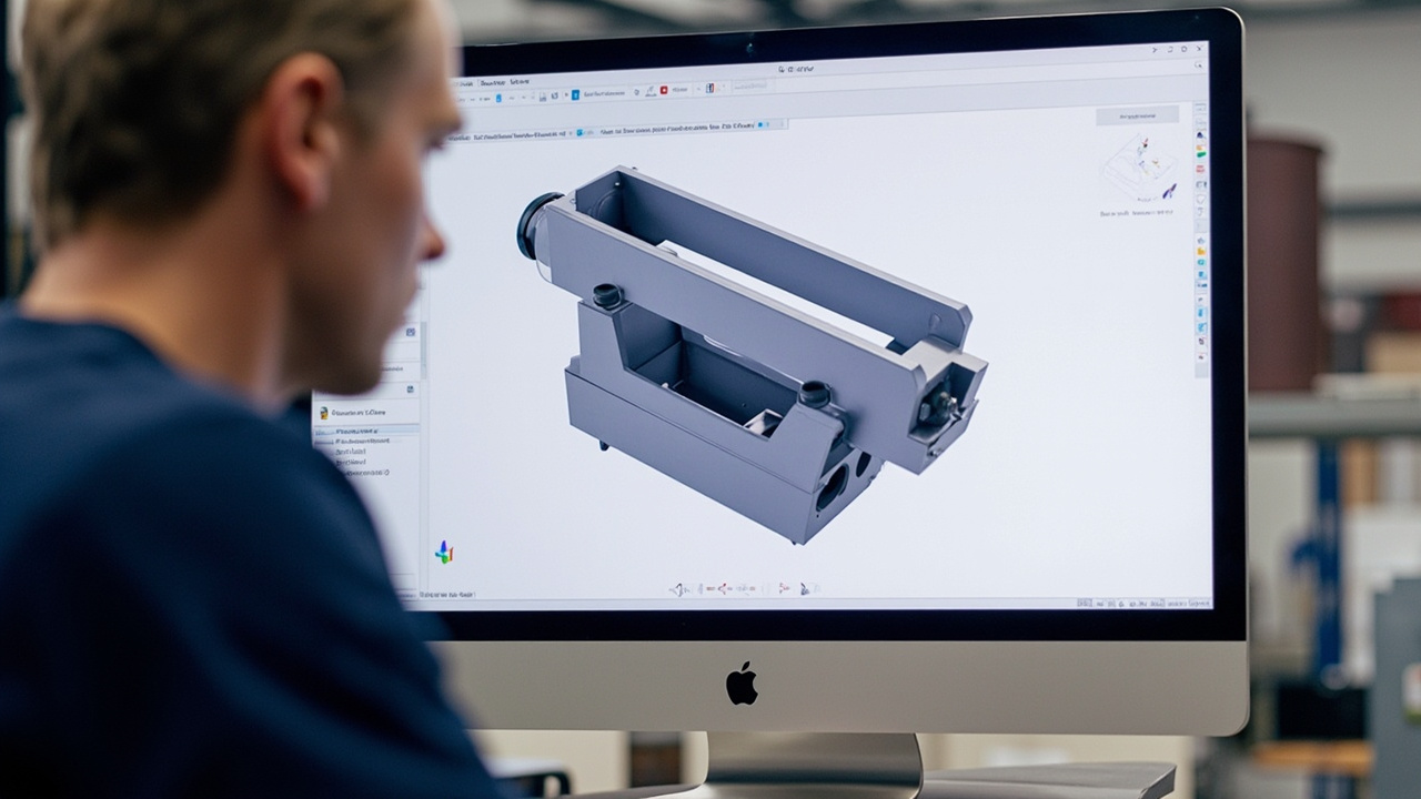
Phase 3: CAD Design and Tooling Development
With feasibility confirmed, engineers proceed to detailed computer-aided design of the bowl geometry, track configuration, and orientation tooling.
Bowl Geometry Design
The bowl's spiral track is designed in CAD software, typically SolidWorks or AutoCAD, with precise control over track width, pitch, wall height, and surface finish. Track width must exceed the part's maximum width by 1.5-2 times to allow free movement while preventing crosswise jamming. Wall height must contain the part in all orientations.
For parts requiring gentle handling, the track profile may include radiused edges, reduced wall angles, or polyurethane lining. For parts with high friction coefficients, the track surface may be polished or coated to reduce drag and ensure consistent movement.
Orientation Tooling Design
Orientation tooling is the most engineering-intensive aspect of custom feeder design. Common tooling elements include gravity selectors that drop incorrectly oriented parts back into the bowl, mechanical selectors that reorient parts using ramps and slots, air-jet selectors that blow lightweight parts into correct orientation, and flipper mechanisms that invert parts mid-track.
Each tooling element is modeled in CAD and analyzed for interaction with the part. Engineers simulate part movement through selectors to predict orientation yield before manufacturing. Finite element analysis may be used for complex mechanical selectors to ensure structural integrity under vibration.
Drive Unit and Base Design
The drive unit must generate sufficient force to move parts up the track while maintaining stable amplitude. Engineers calculate required drive power based on bowl mass, part mass, track inclination, and target feed rate. Spring pack configuration is designed to achieve the desired vibration frequency and amplitude characteristics.
Phase 4: Prototype Manufacturing
Prototype manufacturing transforms CAD designs into physical hardware for testing and validation.
CNC Machining and Fabrication
Bowl prototypes are typically machined from stainless steel blanks on CNC lathes and milling centers. Modern 5-axis CNC machines can produce complex track geometries and tooling features in a single setup, improving accuracy and reducing lead time. For large bowls or complex shapes, fabrication may combine welded segments with final CNC finishing.
Tooling inserts and specialized selectors are machined separately and fitted to the bowl during assembly. Precision tolerances of 0.1-0.2 mm are maintained for critical features to ensure consistent part interaction.
Drive Integration and Controller Setup
The electromagnetic drive unit is mounted to the bowl through the spring pack, with careful attention to alignment and preload. Controller parameters are initially set based on engineering calculations, then refined during testing. Digital controllers with frequency adjustment allow fine-tuning of vibration characteristics to match the part's response.
Preliminary Testing
Before customer demonstration, manufacturers conduct internal testing to verify basic functionality. This includes checking that parts move smoothly up the track, orientation tooling discriminates correctly, feed rate is within specification range, and no excessive noise or vibration is present. Issues identified at this stage are corrected before formal acceptance testing.
Phase 5: Testing and Optimization
Testing with production parts validates design performance and identifies opportunities for optimization.
Feed Rate and Orientation Yield Testing
The primary metrics for feeder validation are sustained feed rate and orientation yield. Engineers run the feeder for extended periods, typically 2-4 hours, measuring actual parts per minute at the discharge point and counting correctly oriented parts versus rejects. Target orientation yield is typically 98-99.5% depending on application requirements.
If feed rate is below specification, engineers adjust vibration amplitude, controller frequency, or track pitch. If orientation yield is insufficient, tooling geometry is refined: selector angles adjusted, air jet pressures modified, or additional tooling steps added.
Part Condition Assessment
After extended running, sample parts are inspected for surface damage, dimensional changes, or coating wear. Parts with delicate finishes may show scuff marks or edge rounding if track surfaces are too aggressive. Polyurethane coating thickness or track edge radii may be adjusted to eliminate damage while maintaining feed performance.
Environmental and Integration Testing
If the feeder will operate in special environments, testing may include temperature cycling, humidity exposure, or cleanroom particle emission measurement. Integration testing with downstream equipment verifies that the discharge height, part spacing, and signal interfaces meet system requirements.
Cost Drivers in Custom Vibratory Feeder Design
Custom feeder costs reflect the engineering effort, manufacturing complexity, and testing rigor invested in the project. Understanding these drivers helps buyers evaluate quotations and identify optimization opportunities.
Engineering Time
Engineering is the largest cost component for custom feeders. Part analysis and orientation study require 4-8 hours. CAD design of bowl and tooling requires 10-25 hours depending on complexity. CAM programming for CNC machining adds 3-8 hours. Testing and optimization requires 5-15 hours. At typical engineering rates, this labor represents 30-50% of total project cost.
Manufacturing Complexity
CNC machining time scales with bowl size and tooling intricacy. A simple 250 mm bowl with one selector requires 6-10 hours of machining. A 500 mm bowl with four cascading selectors, air jet ports, and custom discharge geometry requires 25-40 hours. Material costs are modest in comparison, typically 5-15% of total cost for stainless steel bowls.
Number of Design Iterations
Most custom feeders require 1-2 design iterations after initial testing. Each iteration involves design modification, re-machining of tooling features, and re-testing. Iterations add 20-40% to engineering and machining costs. Buyers can minimize iterations by providing accurate part samples, clear specifications, and prompt feedback during testing.
Special Materials and Coatings
Standard SUS304 stainless steel is adequate for most applications. Upgrades to SUS316L for corrosion resistance or pharmaceutical compliance add 25-35%. Polyurethane coating for gentle handling adds $200-600. Anti-wear coatings for abrasive parts add $300-800 but extend service life significantly.
Timeline Management and Acceleration Strategies
Custom vibratory feeder projects typically take 6-12 weeks from RFQ to delivery. Several strategies can accelerate timelines without compromising quality.
Parallel Processing
Experienced manufacturers parallelize activities where possible. Engineering review and initial CAD modeling can overlap. Controller programming can proceed while the bowl is being machined. Packaging and documentation preparation can occur during final testing. Effective project management reduces total timeline by 15-25%.
Early Sample Provision
Shipping part samples immediately after RFQ submission, rather than waiting for quotation acceptance, allows engineers to begin analysis earlier. Express international shipping costs $50-150 but can save 3-5 days on the critical path.
Clear and Prompt Communication
Delays often occur when buyers take several days to respond to design questions or test reports. Establishing a dedicated communication channel and committing to 24-hour response times keeps the project moving. Video conferences for test demonstrations eliminate travel delays and enable real-time feedback.
Frequently Asked Questions
How long does custom vibratory feeder design typically take?
From RFQ to delivery, custom vibratory feeder projects typically require 6-12 weeks. Simple designs with straightforward parts may be completed in 4-6 weeks. Complex projects with multiple orientation steps, vision integration, or special materials can extend to 14-16 weeks. Rush programs with dedicated engineering resources can reduce timelines by 20-30% for urgent needs.
What information do I need to provide for a custom feeder quotation?
Essential information includes physical part samples or detailed CAD drawings, target feed rate, required discharge orientation, part material and surface finish, production environment details, and downstream equipment interface requirements. The more complete your initial information, the more accurate the quotation and the fewer design iterations required.
Why are custom feeders so much more expensive than standard ones?
Custom feeders require dedicated engineering analysis, bespoke CAD design, CNC machining of unique tooling, and iterative testing that standard feeders do not. A custom project typically involves 30-80 hours of engineering and manufacturing labor versus 4-8 hours for a standard unit. This engineering investment is necessary when your part geometry falls outside common categories.
Can I modify a standard feeder instead of going fully custom?
For moderately complex parts, semi-custom solutions that adapt standard bowl designs with part-specific tooling inserts can reduce cost by 40-60% compared to fully custom designs. This approach works when the part's basic geometry fits an existing bowl category but requires specialized orientation tooling. Discuss semi-custom options with your manufacturer during the quotation phase.
What happens if the prototype does not meet specifications?
Reputable manufacturers include design iteration in their project scope. If initial testing reveals performance gaps, engineers analyze root causes, modify tooling or parameters, and re-test. Most projects achieve specification within 1-2 iterations. At Huben Automation, we do not consider a project complete until the feeder meets agreed performance criteria.
How can I reduce custom feeder costs without compromising performance?
Cost reduction strategies include accepting semi-custom designs where possible, being flexible on non-critical specifications, providing accurate part samples to minimize iterations, consolidating multiple feeder orders for volume pricing, and selecting standard materials and controllers unless special requirements dictate otherwise. Clear communication of true needs versus nice-to-haves prevents over-engineering.
Conclusion: Partnering for Custom Feeder Success
Custom vibratory feeder design is a collaborative process that transforms unique production challenges into reliable automation solutions. Success depends on clear requirements, realistic expectations, and partnership with an experienced manufacturer who understands both the engineering principles and the practical realities of production environments.
The investment in custom design pays dividends through improved feed reliability, higher orientation yields, reduced downtime, and longer service life. When standard feeders cannot meet your part's demands, the custom design process ensures that your automation system performs at its full potential.
Ready to start your custom vibratory feeder project? Contact the Huben Engineering Team with your part details and production requirements. We guide every client through the complete design process with transparent communication, detailed documentation, and commitment to performance outcomes.
Pronto para Automatizar sua Produção?
Receba uma consulta gratuita e orçamento detalhado em até 12 horas da nossa equipe de engenharia.


