Automatic Parts Feeder Systems: Complete Guide for Buyers 2026
Introduction to Automatic Parts Feeder Systems
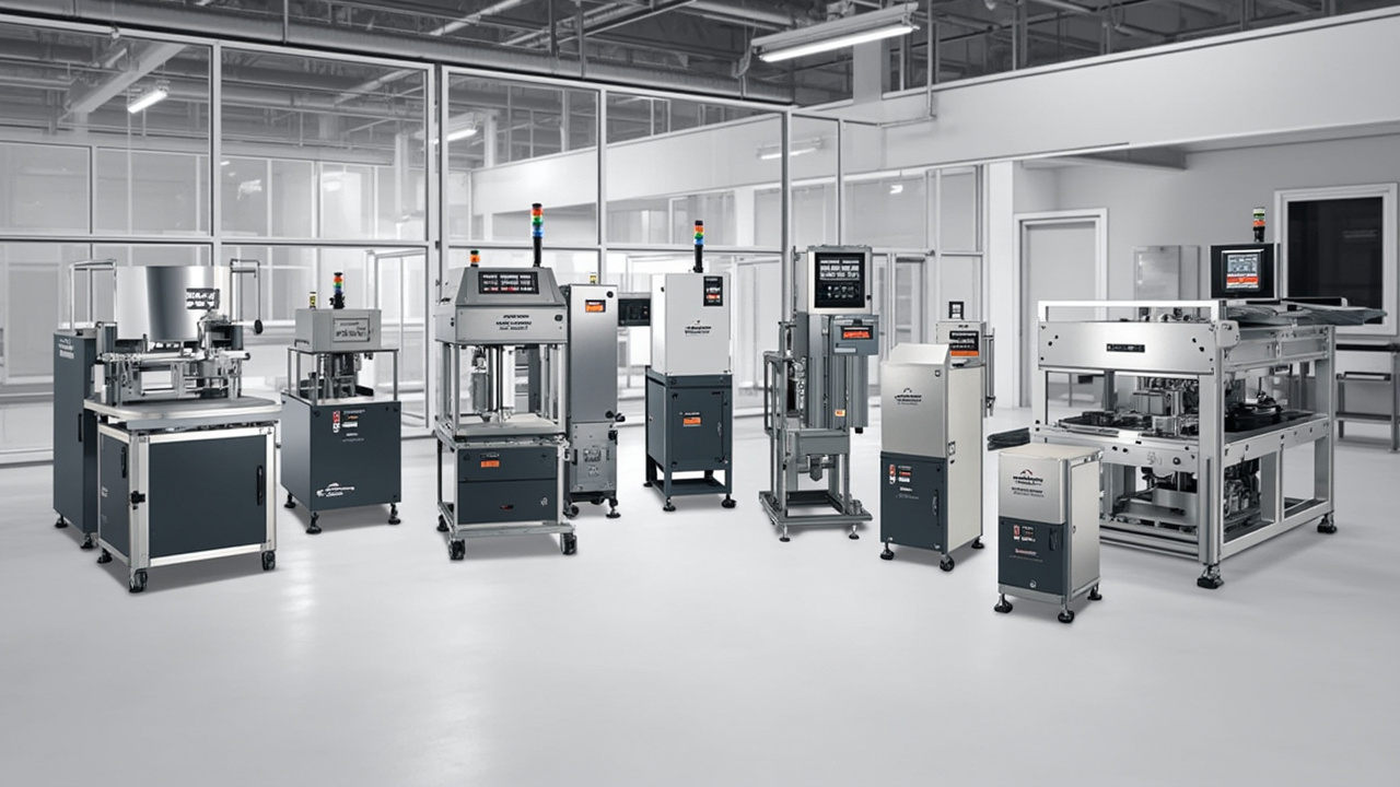
An automatic parts feeder system is the critical first link in any automated production line. It transforms a random mass of components into a controlled stream of singulated, correctly oriented parts ready for assembly, packaging, inspection, or further processing. Without reliable feeding, even the most sophisticated robots, vision systems, and assembly machines cannot operate at their designed capacity.
For buyers and manufacturing engineers evaluating automation investments in 2026, understanding the full landscape of automatic parts feeding technology is essential. This guide provides a comprehensive overview of feeder types, selection methodologies, integration considerations, and cost factors. Whether you are automating a single station or designing a complete production line, the information here will help you make informed decisions that deliver reliable performance and strong return on investment.
The global market for automatic parts feeding equipment continues to grow as manufacturers seek to reduce labor costs, improve consistency, and increase throughput. Chinese manufacturers have emerged as leaders in this field, offering advanced technology at competitive prices with quality that meets or exceeds international standards. Learn more about sourcing automation equipment from China.
Types of Automatic Parts Feeders
Automatic parts feeder systems encompass several distinct technologies, each optimized for specific part characteristics, production volumes, and operational requirements. Understanding these types is the foundation of effective feeder selection.
Vibratory Bowl Feeders
Vibratory bowl feeders are the most widely used automatic parts feeding solution. They use electromagnetic vibration to move parts up a spiral track inside a bowl-shaped container. Custom-designed tooling orients components as they travel, allowing only correctly positioned parts to exit. Bowl feeders handle an enormous range of part sizes and geometries, from tiny electronic components to large automotive parts.
Feed rates: 20 to 800 parts per minute depending on part size and complexity.
Part size range: Approximately 5 mm to 300 mm.
Best for: High-volume production of single part types where mechanical orientation is feasible.
Linear Vibratory Feeders
Linear vibratory feeders transport pre-oriented parts along a straight track. They do not orient parts from a random state; instead, they maintain and convey orientation established by an upstream bowl feeder or other device. Linear feeders bridge the gap between orientation equipment and downstream processes, providing controlled transport over distances from 100 mm to over 2,000 mm.
Feed rates: 10 to 400 parts per minute.
Part size range: 5 mm to 200 mm.
Best for: Transporting oriented parts between stations, buffering, and presenting parts to robotic pick stations.
Centrifugal Feeders
Centrifugal feeders use rotational force rather than vibration to orient and feed parts. A spinning disc propels parts outward to a peripheral track where orientation tooling selects correctly positioned components. The continuous rotational motion enables very high feed rates and gentler handling than vibration for suitable parts.
Feed rates: 100 to 1,500+ parts per minute.
Part size range: 10 mm to 80 mm.
Best for: Simple symmetrical parts requiring high-speed feeding with low noise.
Flexible Vibratory Feeders
Flexible feeders represent the newest generation of parts feeding technology. They combine a programmable vibrating platform with machine vision and robotic picking. Parts are spread on a flat surface by programmable vibration patterns. A camera identifies part positions and orientations, and a robot picks correctly oriented parts. No mechanical tooling is required, enabling rapid changeover between different parts.
Feed rates: 10 to 200 parts per minute depending on part size and robot speed.
Part size range: 5 mm to 150 mm.
Best for: High-mix, low-volume production where frequent changeovers make mechanical tooling uneconomical.
Step Feeders
Step feeders use mechanically driven steps or plates to lift parts from a bulk hopper to a discharge height. Orientation occurs at the discharge point through gravity slides or mechanical selectors. The step motion is gentler than vibration, making these feeders suitable for large, heavy, or fragile components.
Feed rates: 10 to 100 parts per minute.
Part size range: 50 mm to 500 mm.
Best for: Large, heavy, or delicate parts that cannot tolerate vibration.
Hopper Elevators and Bulk Feeders
While not feeders in the orientation sense, hopper elevators and bulk feeders are essential components of complete feeding systems. They store bulk parts and deliver them at a controlled rate to the orienting feeder. Proper hopper sizing and elevator type ensure the orienting feeder never starves or overflows.
| Feeder Type | Orientation Method | Feed Rate (ppm) | Part Size | Changeover Time | Relative Cost |
|---|---|---|---|---|---|
| Vibratory Bowl | Mechanical tooling | 20-800 | 5-300 mm | 30 min - 4 hrs | Low-Medium |
| Linear Vibratory | None (transport only) | 10-400 | 5-200 mm | 15-60 min | Low |
| Centrifugal | Gravity/centrifugal | 100-1,500 | 10-80 mm | 30 min - 2 hrs | Medium-High |
| Flexible | Vision-guided robot | 10-200 | 5-150 mm | 5-15 min | High |
| Step Feeder | Gravity/mechanical | 10-100 | 50-500 mm | 30 min - 2 hrs | Medium |
Feeder Selection Criteria
Selecting the right automatic parts feeder requires systematic evaluation across multiple dimensions. A structured selection process prevents costly mismatches between equipment capability and production requirements.
Part Characteristics Analysis
Begin with comprehensive documentation of the parts to be fed. Critical characteristics include:
- Dimensions — Overall size, weight, and dimensional tolerances affect track design and drive sizing.
- Geometry — Symmetrical parts orient more easily than asymmetric ones. Features like holes, slots, and flats provide orientation reference points.
- Material — Material density, hardness, and surface finish influence vibration response and wear characteristics.
- Surface sensitivity — Painted, plated, or polished surfaces may require gentle handling, polyurethane coatings, or non-contact transport.
- Fragility — Thin-walled, brittle, or delicate parts need reduced vibration amplitude or alternative feeding technologies.
- Cohesiveness — Oily, magnetic, or statically charged parts may cling together and require special handling.
Always provide physical part samples to your feeder manufacturer, including acceptable dimensional variations and defective examples. Computer models and drawings cannot substitute for handling real parts.
Production Requirements
Define your production parameters with precision:
- Required feed rate — Parts per minute needed by downstream equipment, plus margin for transient demands.
- Orientation specification — Exact attitude required: which feature up, which direction forward, rotational position.
- Production volume — Annual quantity, daily run hours, and expected equipment lifetime.
- Product mix — Single part or multiple parts? If multiple, how frequently do changeovers occur?
- Future flexibility — Will part designs change? Will new products be added to the line?
Environmental and Regulatory Factors
The operating environment significantly influences feeder design:
- Cleanliness — Cleanrooms require stainless steel construction, sealed drives, and minimal particle generation.
- Temperature and humidity — Extreme conditions affect material properties and electrical components.
- Noise limits — Workplace regulations may require acoustic enclosures or low-noise designs.
- Hygiene requirements — Food, pharmaceutical, and medical applications demand specific materials and surface finishes.
- Explosion risk — Hazardous environments may require ATEX-certified equipment.
Integration with Downstream Equipment
A parts feeder never operates in isolation. Successful integration requires planning for:
- Interface geometry — Height, position, and orientation of the discharge point relative to downstream equipment.
- Communication protocols — Digital I/O, fieldbus, or Ethernet communication with the line controller.
- Cycle time matching — Feeder output must synchronize with downstream consumption to prevent starvation or overflow.
- Buffer capacity — Sufficient accumulation between feeder and consumer to handle transient mismatches.
Huben Expert Tip
When evaluating feeder options, always request a feed test with your actual production parts before committing to purchase. Reputable manufacturers will demonstrate feeder performance with your samples and provide video documentation of feed rates, orientation accuracy, and part condition after feeding.
System Integration Considerations
Modern automatic parts feeder systems are components of larger automated production ecosystems. Successful integration demands attention to control architecture, safety systems, and physical layout.
Control Architecture
Feeder controllers range from simple variable-voltage units to sophisticated digital systems with network connectivity. Consider these control aspects:
Standalone operation — Basic feeders run independently with simple start/stop signals. Suitable for manual stations or simple automation.
PLC integration — Most production lines use programmable logic controllers to coordinate equipment. Feeders should support standard industrial communication protocols such as digital I/O, RS485, Modbus, Profinet, or Ethernet/IP.
Smart feeding — Advanced feeders include built-in sensors and microprocessors that optimize operation automatically. Features include automatic tuning, feed rate adaptation, jam detection, and predictive maintenance alerts.
Safety and Compliance
Automatic parts feeders must comply with machinery safety standards in your market:
- ISO 12100 — General machinery safety design principles.
- IEC 60204-1 — Electrical equipment of machines.
- CE marking — Required for equipment placed on the European market.
- UL/CSA — North American electrical safety certifications.
Physical safety measures include guarding around moving parts, emergency stop circuits, and lockout-tagout provisions for maintenance. Risk assessment should identify all hazards and specify appropriate mitigation measures.
Physical Layout and Ergonomics
Feeder placement affects both operational efficiency and operator wellbeing:
- Loading height — Bulk parts must be loaded at an ergonomic height or via mechanical lifting equipment.
- Access for maintenance — Sufficient clearance around the feeder for cleaning, adjustment, and component replacement.
- Vibration isolation — Feeders should be mounted on isolation pads to prevent vibration transmission to sensitive equipment.
- Noise management — Acoustic enclosures or strategic placement protect operators from excessive noise exposure.
Cost Factors and Return on Investment
Understanding the full cost picture enables accurate ROI calculations and prevents budget surprises.
Initial Equipment Cost
Equipment costs vary widely by feeder type, size, and complexity:
- Standard vibratory bowl feeder: $1,000 - $3,500
- Custom-tooled bowl feeder: $2,000 - $5,000
- Linear vibratory feeder: $800 - $2,500
- Centrifugal feeder: $3,000 - $8,000
- Flexible vibratory feeder: $5,000 - $15,000
- Step feeder: $2,500 - $6,000
Chinese manufacturers like Huben Automation typically offer prices 40-60% below Western suppliers while maintaining ISO 9001 quality standards. See our detailed price guide.
Tooling and Changeover Costs
Mechanical feeders require custom tooling for each part type. Tooling costs range from $300 to $2,000 per part depending on complexity. For production environments with frequent changeovers, tooling costs can exceed equipment costs over time. Flexible feeders eliminate tooling costs but have higher initial investment.
Operating Costs
Ongoing operating costs include electricity, compressed air for pneumatic systems, routine maintenance consumables, and labor for cleaning and adjustment. Vibratory feeders typically consume 100-500 watts depending on bowl size. Annual maintenance costs average 5-10% of equipment cost for well-maintained systems.
ROI Calculation
The return on investment for automatic parts feeding equipment comes from multiple sources:
- Labor reduction — Eliminating manual part loading and orientation.
- Throughput increase — Higher and more consistent feed rates than manual operation.
- Quality improvement — Consistent orientation reduces assembly errors and defects.
- Reduced injury risk — Automated handling eliminates repetitive strain injuries from manual feeding.
- Floor space optimization — Compact feeders replace manual workstations.
Typical payback periods for automatic parts feeder systems range from 6 to 18 months depending on labor costs, production volume, and equipment cost. Use our ROI calculator to estimate payback for your specific application.
The Buying Process
A structured buying process ensures you receive equipment that meets your requirements and performs reliably in production.
Step 1: Define Requirements
Document your part characteristics, production requirements, environmental conditions, and integration needs. The more detailed your specification, the more accurate vendor proposals will be.
Step 2: Request for Quotation
Submit your requirements to qualified manufacturers along with physical part samples. Request detailed proposals including equipment specifications, performance guarantees, delivery schedule, and warranty terms. Download our RFQ checklist to ensure you cover all essential elements.
Step 3: Evaluate Proposals
Compare proposals on technical merit, not just price. Evaluate:
- Manufacturer experience with similar parts and industries
- Feed test results with your actual parts
- Quality certifications and manufacturing standards
- Warranty coverage and spare parts availability
- Technical support and documentation quality
Step 4: Factory Acceptance Testing
Before shipment, witness or review factory acceptance testing to verify the feeder meets specified performance. Document feed rate, orientation accuracy, and part condition. Address any deviations before the equipment leaves the factory. View our acceptance testing guide.
Step 5: Installation and Commissioning
Proper installation ensures optimal performance. Follow manufacturer guidelines for mounting, electrical connection, and vibration isolation. Commissioning includes tuning the feeder for your specific parts and verifying integration with downstream equipment.
Frequently Asked Questions
What is the most reliable type of automatic parts feeder?
Vibratory bowl feeders have the longest track record of reliability in industrial applications. With proper design and maintenance, they operate continuously for 15-25 years. Their simple mechanical design—no rotating parts, bearings, or chains—contributes to exceptional uptime. The key to reliability is matching the feeder design to the specific part and application. A well-designed bowl feeder for a suitable part will outperform more complex technologies in long-term reliability.
How do I calculate the required feed rate for my application?
Start with your downstream equipment cycle time. If your assembly machine operates at 60 cycles per minute, you need at least 60 parts per minute. Add a safety margin of 20-30% to account for transient demands, feeder inefficiency, and occasional misfeeds. Consider whether the downstream process runs continuously or intermittently—intermittent operation may allow a smaller feeder with buffer accumulation. Always specify feed rate in parts per minute at the feeder discharge point, not just theoretical bowl capacity.
Can automatic parts feeders handle delicate or surface-sensitive components?
Yes, with proper design. Options for delicate parts include polyurethane-coated bowls that cushion parts and reduce impact, reduced vibration amplitude with frequency optimization, centrifugal feeders that avoid vibration entirely, and flexible feeders with gentle robotic handling. For surface-sensitive parts like painted or plated decorative components, specify non-marking bowl materials, controlled drop heights, and elimination of metal-to-metal contact points. Provide samples of your most delicate parts for feed testing.
What is the typical delivery time for a custom automatic parts feeder?
Delivery times vary by manufacturer and feeder complexity. Standard bowl feeders with minimal customization typically ship in 2-4 weeks. Custom-tooled bowl feeders require 4-8 weeks for design, fabrication, and testing. Complex flexible feeding systems or multi-feeder integrated lines may require 8-12 weeks. Chinese manufacturers like Huben Automation often achieve shorter lead times than European or North American suppliers due to integrated manufacturing capabilities. Always confirm delivery schedules before placing orders, especially for time-critical projects.
How much training is required for operators and maintenance staff?
Basic operation of automatic parts feeders requires minimal training—typically a few hours to understand loading procedures, start/stop controls, and simple adjustments. Maintenance training covers spring inspection, cleaning procedures, tooling replacement, and controller settings, usually requiring 1-2 days. Flexible feeders with vision systems require additional training on recipe management, camera calibration, and robot programming. Reputable manufacturers provide comprehensive documentation and on-site training as part of the equipment package.
Should I buy from a local distributor or directly from the manufacturer?
Buying directly from the manufacturer offers significant advantages: lower prices by eliminating distributor margins, direct access to engineering expertise for application support, faster response to technical questions, and more flexible customization options. The main consideration is whether the manufacturer provides adequate local support for installation and service. Established Chinese manufacturers like Huben Automation serve global customers with English-speaking engineering support, detailed documentation, video conferencing for remote assistance, and comprehensive spare parts programs. For most buyers, direct purchase from an experienced manufacturer delivers better value than distributor channels. Read our guide on buying direct vs. through trading companies.
Conclusion
Automatic parts feeder systems are essential investments for modern manufacturing operations seeking to improve efficiency, consistency, and cost-effectiveness. The technology landscape offers solutions for virtually every application—from high-speed vibratory bowl feeders for automotive fasteners to flexible vision-guided systems for high-mix electronics assembly.
Success begins with thorough understanding of your requirements: part characteristics, production volumes, environmental conditions, and integration needs. Armed with this knowledge, you can evaluate feeder types objectively and select the technology that delivers the best performance and value for your specific application.
The buying process demands attention to detail at every stage, from initial specification through factory acceptance testing and commissioning. Partnering with an experienced manufacturer who understands both feeder technology and your industry's unique requirements transforms a complex purchase into a smooth implementation.
Huben Automation manufactures the full range of automatic parts feeder systems and provides comprehensive application engineering support. With over 20 years of experience and 200+ successful projects worldwide, we help customers select, integrate, and optimize feeding solutions that deliver measurable production improvements.
Ready to discuss your automatic parts feeding requirements? Contact the Huben Engineering Team for a free application review, feed test, and detailed quotation.
Pronto para Automatizar sua Produção?
Receba uma consulta gratuita e orçamento detalhado em até 12 horas da nossa equipe de engenharia.


