Centrifugal Feeders vs Vibratory Bowl Feeders: Complete Comparison
What Is a Centrifugal Feeder?
A centrifugal feeder, also known as a rotary feeder, disc feeder, or centrifugal bowl feeder, is an automated parts handling device that uses rotational force rather than vibration to orient and feed components. Parts are placed onto a rotating disc or bowl, and centrifugal force propels them outward along a peripheral track where orientation tooling selects correctly positioned parts for discharge.
Centrifugal feeders occupy an important niche in the parts feeding landscape. They excel at high-speed feeding of simple, symmetrical parts where their gentle rotational motion and exceptional throughput provide advantages over vibratory technology. Understanding when centrifugal feeding is the better choice—and when vibratory bowls remain superior—enables manufacturing engineers to optimize their automation investments.
This guide provides a comprehensive comparison of centrifugal and vibratory feeding technologies, examining operating principles, performance characteristics, application suitability, and total cost of ownership. See our earlier comparison article for a quick overview, or read on for the complete technical analysis.
How Centrifugal Feeders Work
The operating principle of a centrifugal feeder is fundamentally different from vibratory technology, though both achieve the same end goal: delivering oriented parts at a controlled rate.
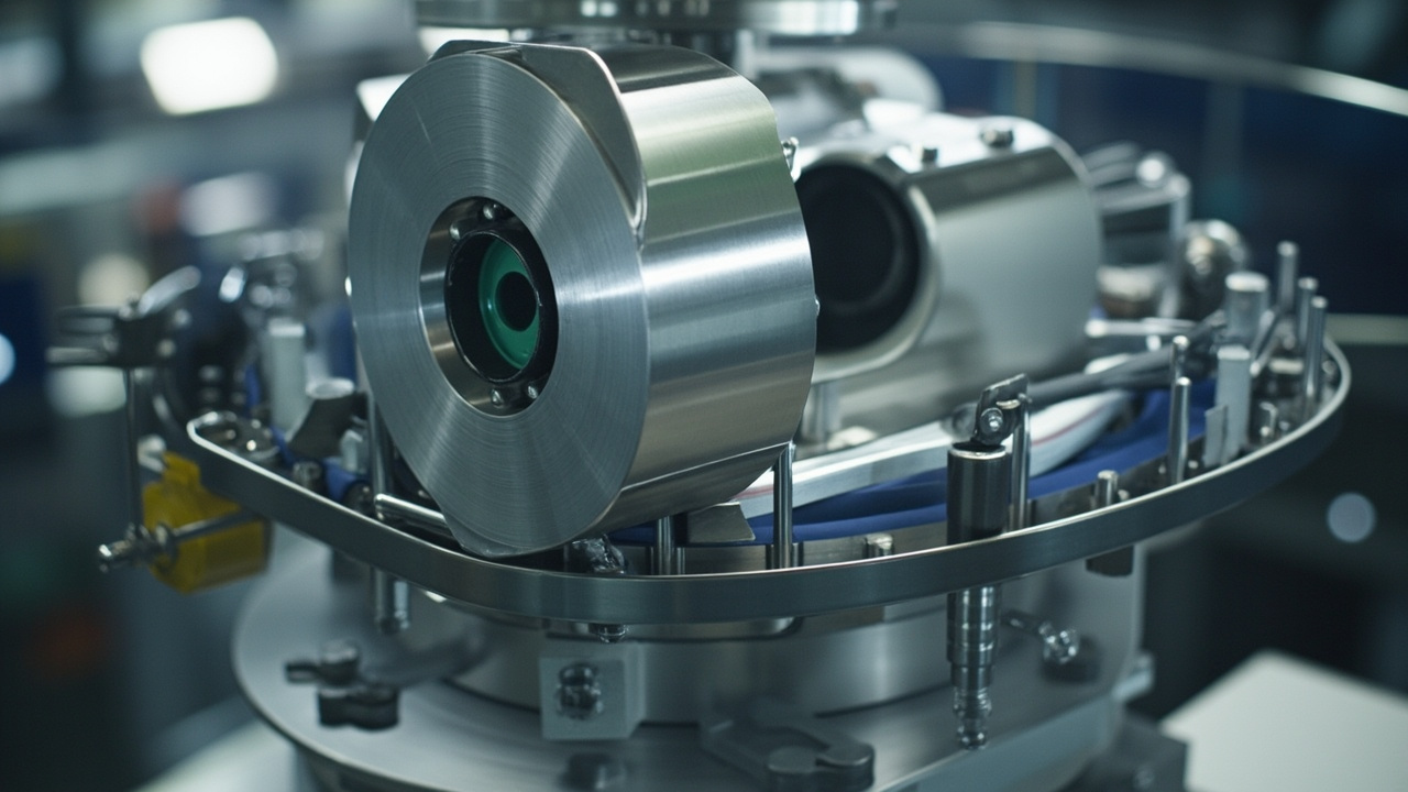
Rotational Drive System
The heart of a centrifugal feeder is a motor-driven rotating disc or shallow bowl. The drive system typically uses an AC induction motor with variable speed control, though servo motors are increasingly common for applications requiring precise speed regulation. The motor rotates the disc at controlled speeds, typically ranging from 30 to 300 revolutions per minute depending on part size and desired feed rate.
Unlike vibratory feeders that oscillate back and forth, centrifugal feeders rotate continuously in one direction. This continuous motion eliminates the pulsating flow characteristic of vibratory feeding and produces smoother, more consistent part delivery.
Centrifugal Force and Part Movement
As the disc rotates, parts experience centrifugal force that pushes them outward toward the disc perimeter. The magnitude of this force depends on rotational speed and part mass—heavier parts and higher speeds generate greater outward force. Parts slide or roll across the disc surface until they reach the peripheral track.
The disc surface may be flat, slightly concave, or feature radial ribs depending on the application. Flat surfaces work well for parts that slide easily. Concave surfaces help contain parts and prevent them from falling off the edge. Radial ribs can help engage with part features to ensure positive outward movement.
Peripheral Track and Orientation Tooling
At the disc perimeter, parts enter a track that follows the circumference. This track incorporates orientation tooling similar in concept to vibratory bowl feeders but adapted for rotational motion. Common tooling elements include:
- Selectors — Narrow track sections that allow only parts in the correct orientation to pass.
- Flipper rails — Features that use part center of gravity to rotate parts into the desired attitude.
- Air jets — Pneumatic assistance for lightweight parts or to clear jams.
- Recirculation channels — Paths that return rejected parts to the disc center for another attempt.
The orientation process occurs as parts travel along the peripheral track. Correctly oriented parts continue to the discharge point; misoriented parts are directed back to the disc center via recirculation channels or simply fall back onto the rotating disc.
Discharge and Integration
At the discharge point, oriented parts exit the feeder through a chute or transition to a linear track. The discharge can be continuous or controlled by an escapement mechanism that releases parts one at a time on demand from downstream equipment. Because centrifugal feeders often operate at very high speeds, escapements are commonly used to match feeder output to downstream cycle times.
Huben Expert Tip
The relationship between disc speed and feed rate is not linear. Doubling the rotational speed more than doubles the centrifugal force, which can cause parts to tumble or damage. Optimal speed is determined empirically through testing with actual production parts. Always start at low speed and increase gradually while observing part behavior.
Centrifugal vs Vibratory: Detailed Comparison
Both centrifugal and vibratory feeders solve the same fundamental problem—orienting and feeding parts—but they do so through different physical mechanisms, each with distinct advantages and limitations.
Speed and Throughput
Centrifugal feeders achieve significantly higher feed rates than vibratory bowls for suitable parts. Rates of 1,000 to 3,000 parts per minute are common, with some applications exceeding 5,000 parts per minute for small, simple components. This speed advantage comes from the continuous rotational motion, which does not have the inherent speed limitations of vibratory micro-step movement.
Vibratory bowl feeders typically achieve 200 to 800 parts per minute, with specialized designs reaching 1,000 parts per minute for small parts. The vibratory motion involves parts lifting and settling with each cycle, which limits maximum speed.
Part Geometry Suitability
Centrifugal feeders work best with simple, symmetrical parts that orient easily through gravity and centrifugal force. Ideal parts include screws, bolts, pins, rivets, washers, discs, balls, and simple cylindrical or disc-shaped components. Parts with complex asymmetry, flexible features, or irregular shapes often cannot be oriented reliably in centrifugal systems.
Vibratory bowl feeders handle a much broader range of part geometries. The custom tooling in a vibratory bowl can orient parts with complex features, asymmetrical shapes, and multiple possible orientations. Parts with holes, slots, tabs, and other features that can engage with mechanical selectors are well-suited to vibratory orientation.
Part Handling Gentleness
Centrifugal feeders are generally gentler on parts than vibratory feeders. The continuous rotational motion avoids the repeated impact and abrasion that occurs in vibratory bowls where parts vibrate against each other and the track surface. This gentleness makes centrifugal feeders suitable for delicate parts with surface finishes that must be protected.
However, the high speeds achievable in centrifugal feeders can create problems. Parts moving at high velocity may damage each other through collision at the disc perimeter or discharge point. Careful design of recirculation paths and discharge chutes is essential to prevent part-to-part damage.
Noise Levels
Centrifugal feeders are noticeably quieter than vibratory feeders. Typical noise levels range from 65 to 75 dB(A) compared to 75 to 90 dB(A) for vibratory bowls. The absence of high-frequency vibration and the smooth rotational motion contribute to lower noise emission. For noise-sensitive environments, this can be a significant advantage.
Energy Efficiency
At high throughput rates, centrifugal feeders can be more energy-efficient than vibratory feeders per part fed. The rotational drive operates at relatively constant power regardless of feed rate, while vibratory feeders consume power proportional to vibration amplitude. For very high-speed applications, the energy advantage of centrifugal feeding becomes meaningful.
Maintenance Requirements
Centrifugal feeders have fewer wear parts than vibratory feeders. There are no springs to fatigue, no coils to overheat, and no armature gaps to maintain. The main wear items are bearings in the drive system and the disc/track surface where parts slide. Bearing replacement every 5-10 years and occasional track resurfacing constitute the bulk of maintenance.
Vibratory feeders require periodic spring replacement, coil inspection, and tuning adjustments. Springs typically last 3-5 years under continuous operation. Coils may need replacement after 5-8 years. The simpler mechanical design of centrifugal feeders translates to lower maintenance burden and higher uptime.
| Characteristic | Centrifugal Feeder | Vibratory Bowl Feeder |
|---|---|---|
| Feed Rate | 1,000-3,000+ ppm | 200-800 ppm |
| Part Complexity | Simple, symmetrical | Simple to complex |
| Orientation Axes | 1-2 axes | Multi-axis |
| Part Fragility | Good (gentle rotation) | Moderate (vibration) |
| Noise Level | 65-75 dB(A) | 75-90 dB(A) |
| Initial Cost | $3,000-$8,000 | $1,000-$5,000 |
| Maintenance | Low (bearings, track) | Moderate (springs, coils) |
| Changeover | 30 min - 2 hrs | 30 min - 4 hrs |
| Energy per Part (high volume) | Lower | Higher |
| Multi-Part Capability | No | No (without retooling) |
When to Choose a Centrifugal Feeder
Centrifugal feeders are the optimal choice when your application matches their strengths. Consider centrifugal feeding when:
Parts Are Simple and Symmetrical
Parts with regular cylindrical, disc, or spherical shapes orient naturally under centrifugal force. Screws, bolts, rivets, pins, washers, balls, and simple caps are ideal candidates. The part should have a clear natural resting orientation that gravity and centrifugal force can establish reliably.
Very High Feed Rates Are Required
When your production line demands 1,000 parts per minute or more, centrifugal feeders often provide the only practical solution. High-speed packaging lines, pharmaceutical cap feeders, and cosmetic assembly operations frequently require the throughput that centrifugal technology delivers.
Parts Have Sensitive Surfaces
The gentle rotational motion of centrifugal feeders causes less surface damage than vibratory feeding. Parts with polished, plated, painted, or decorated finishes may be better preserved in a centrifugal system. The absence of high-frequency vibration eliminates the micro-abrasion that can dull polished surfaces over time.
Noise Reduction Is Important
For installations in noise-sensitive environments—cleanrooms, medical device facilities, or workplaces near office areas—the lower noise emission of centrifugal feeders may eliminate the need for expensive acoustic enclosures. The 10-15 dB noise reduction compared to vibratory feeders can be the deciding factor.
Production Runs Are Long and Stable
Like vibratory bowl feeders, centrifugal feeders require custom tooling for each part type. They are most economical when dedicated to a single part number for extended production runs. The higher initial cost is justified by lower operating costs and reduced maintenance over time.
When Vibratory Bowl Feeders Remain Superior
Despite the advantages of centrifugal feeders, vibratory bowl feeders remain the better choice for many applications:
Complex Part Geometries
Parts with asymmetric features, multiple possible orientations, or complex shapes that cannot be oriented by gravity alone require the custom mechanical tooling of vibratory bowls. The ability to design selectors, wipers, and chutes that engage with specific part features makes vibratory feeders uniquely capable for complex orientation challenges.
Multi-Axis Orientation Requirements
When parts must exit with specific features facing a precise direction in multiple axes, vibratory bowl tooling can achieve orientations that centrifugal systems cannot. The spiral track provides multiple opportunities for orientation correction as parts travel.
Delicate or Flexible Parts
While centrifugal feeders are gentle in terms of surface contact, the high speeds can cause damage through collision. Very delicate parts, flexible components like O-rings or gaskets, and parts with thin walls may be damaged by the centrifugal force or collisions at the disc perimeter. Vibratory feeders with reduced amplitude and polyurethane coatings can handle these parts more safely.
Budget Constraints
Standard vibratory bowl feeders cost significantly less than centrifugal feeders. For applications where either technology could work, the lower initial cost of vibratory feeding may be decisive. This is particularly true for lower-speed applications where the throughput advantage of centrifugal feeding is not needed.
Small Part Size Range
Centrifugal feeders have a narrower optimal part size range than vibratory feeders. Very small parts (under 10 mm) may not generate sufficient centrifugal force for reliable movement. Very large parts (over 80 mm) require impractically large discs and may not orient well. Vibratory bowls accommodate a wider size spectrum.
Hybrid Feeding Systems
Many production lines benefit from combining centrifugal and vibratory technologies in hybrid configurations that leverage the strengths of each.
Centrifugal Bowl with Vibratory Inline Track
The most common hybrid arrangement uses a centrifugal feeder for high-speed bulk orientation, followed by a vibratory linear track for precise transport and presentation to downstream equipment. The centrifugal unit handles the high-speed bulk feeding; the vibratory track provides controlled, gentle delivery with precise spacing and positioning.
Vibratory Bowl with Centrifugal Accumulator
For applications requiring complex orientation but with intermittent downstream demand, a vibratory bowl can feed into a centrifugal accumulator. The accumulator stores oriented parts during downstream pauses and releases them smoothly when demand resumes. This configuration buffers cycle time mismatches while maintaining the orientation capability of the vibratory bowl.
Dual-Feeder Parallel Stations
Some production lines install both centrifugal and vibratory feeders in parallel, each handling different part types or operating at different speeds. This redundancy provides backup capacity and allows production to continue if one feeder requires maintenance.
Design and Selection Considerations
When specifying a centrifugal feeder, several design parameters require careful attention.
Disc Diameter and Speed
Disc diameter determines the track circumference and therefore the available length for orientation tooling. Typical diameters range from 200 mm to 800 mm. Larger discs provide more orientation track length and higher peripheral speeds at a given RPM, but require more powerful drives and occupy more floor space.
Rotational speed is selected based on part size, weight, and desired feed rate. Higher speeds increase throughput but also increase part velocity and potential for damage. Speed is typically variable, allowing optimization during commissioning.
Track and Tooling Design
The peripheral track must be precisely engineered for the specific part. Track width, depth, and surface finish all influence feeding reliability. Orientation tooling is custom-designed based on part geometry analysis and prototype testing. Unlike vibratory bowls where tooling can sometimes be modified in the field, centrifugal feeder tooling is usually fixed at manufacture and requires replacement for different parts.
Drive and Control System
AC motor drives with variable frequency control provide cost-effective speed adjustment. Servo drives offer precise speed control, rapid acceleration, and integration with line control systems. The control system should include soft-start capability to prevent part scattering at startup, speed feedback for consistent operation, and communication interfaces for integration with production line controls.
Material Selection
Disc and track materials must withstand part abrasion while meeting any hygiene or regulatory requirements. Stainless steel is standard for most applications. Hardened steel or wear-resistant coatings extend life in high-volume applications. Food and pharmaceutical applications may require specific grades with full material certification.
Frequently Asked Questions
Can a centrifugal feeder handle the same part types as a vibratory bowl feeder?
No. Centrifugal feeders are limited to simpler, more symmetrical parts that orient reliably through gravity and centrifugal force. Parts with complex asymmetry, multiple stable orientations, or features that interfere with rotational orientation are better suited to vibratory bowl feeders. As a general rule, if a part can be oriented by rolling it on a table, it can probably be fed centrifugally. If it requires specific features to be engaged by mechanical selectors, it likely needs a vibratory bowl. Learn about vibratory bowl feeder capabilities.
Are centrifugal feeders more expensive than vibratory bowl feeders?
Yes, centrifugal feeders typically cost 50-100% more than equivalent vibratory bowl feeders. A standard centrifugal feeder ranges from $3,000 to $8,000 compared to $1,000 to $5,000 for a vibratory bowl. However, the higher initial cost may be offset by lower maintenance costs, higher throughput, and reduced noise management expenses. For high-volume applications where the speed advantage is fully utilized, centrifugal feeders can deliver lower total cost of ownership over time.
How do I know if my parts are suitable for centrifugal feeding?
The best way to determine suitability is to conduct a feed test with actual production parts. Reputable manufacturers will evaluate your parts and demonstrate feeding performance. As preliminary guidance, suitable parts are typically symmetrical (cylindrical, disc, or spherical), have a single natural stable orientation, weigh between 0.5 grams and 200 grams, and have no features that cause nesting or interlocking. Parts with flexible elements, very thin walls, or extreme aspect ratios are usually unsuitable.
What maintenance does a centrifugal feeder require?
Centrifugal feeders require less maintenance than vibratory feeders. Routine maintenance includes inspecting and lubricating drive bearings according to manufacturer schedules, checking and tightening disc mounting bolts, cleaning the disc and track surfaces to remove debris and worn particles, inspecting orientation tooling for wear, and verifying speed control calibration. Drive bearings typically last 5-10 years under continuous operation. The disc/track surface may require resurfacing after several years of high-volume operation. Overall, expect maintenance costs approximately 30-50% lower than equivalent vibratory feeders.
Can centrifugal feeders be used in cleanroom environments?
Yes, with appropriate design. Cleanroom centrifugal feeders use sealed drive systems to prevent particle emission, stainless steel construction for cleanability, and smooth surfaces without crevices where particles could accumulate. The lower vibration of centrifugal feeders actually reduces particle generation compared to vibratory systems, making them attractive for cleanroom applications. Specify your cleanroom class and contamination requirements when requesting quotation.
How do centrifugal and vibratory feeders compare for food and pharmaceutical applications?
Both technologies can be adapted for food and pharmaceutical use with appropriate materials and design. Centrifugal feeders have an advantage in these industries due to their gentler handling and lower noise. The smooth rotational motion is less likely to damage delicate food products or generate the metal particles that vibratory feeders can produce from spring and track wear. However, the choice ultimately depends on part geometry and production requirements. Read our food-grade feeder guide for detailed requirements.
Conclusion
Centrifugal feeders and vibratory bowl feeders represent two complementary approaches to automated parts feeding, each with distinct strengths and ideal applications. Centrifugal feeders excel at high-speed feeding of simple, symmetrical parts with gentle handling and low noise. Vibratory bowl feeders dominate applications requiring complex orientation, broader part size ranges, and lower initial investment.
The choice between these technologies should be based on a thorough analysis of your specific requirements: part geometry, production volume, speed requirements, environmental constraints, and budget. For many high-volume applications with suitable parts, centrifugal feeders deliver superior throughput and lower operating costs that justify their higher initial price. For complex parts or moderate speeds, vibratory bowls remain the proven, cost-effective solution.
Hybrid configurations that combine both technologies can capture the benefits of each: centrifugal feeding for high-speed bulk handling and vibratory transport for precise presentation. The key is matching the technology to the application rather than forcing a one-size-fits-all solution.
Huben Automation manufactures both centrifugal and vibratory feeding systems and provides unbiased application engineering to help you select the optimal technology for your specific parts and production requirements. With over 20 years of experience and expertise across both technologies, we design feeding solutions that deliver measurable performance improvements.
Not sure whether centrifugal or vibratory feeding is right for your application? Contact the Huben Engineering Team for a free part evaluation, feed test, and technology recommendation.
अपने उत्पादन को स्वचालित करने के लिए तैयार हैं?
हमारी इंजीनियरिंग टीम से 12 घंटे के भीतर मुफ्त परामर्श और विस्तृत कोटेशन प्राप्त करें।


