Hopper Elevators & Bulk Feeding Systems: Integration Guide
Why Hopper Elevators Are Critical to Feeding System Performance
A vibratory bowl feeder without a properly sized hopper elevator is like an assembly line without material supply: it works only until the bowl empties. Hopper elevators — also called bulk feeding hoppers, elevator feeders, or simply hopper feeders — are the upstream components that store bulk parts and automatically refill the bowl feeder as its level drops. Despite their essential role, hopper elevators are frequently under-specified, purchased as afterthoughts, or sized by guesswork rather than engineering calculation.
The consequences of poor hopper integration are predictable and costly. An undersized hopper requires frequent manual refilling, wasting operator time and creating production interruptions. An oversized hopper without proper level control floods the bowl, overwhelming orientation tooling and causing jams, recirculation, and reduced feed rates. A hopper of the right capacity but the wrong type for the part material may fail to elevate parts reliably, leaving the bowl starved even when the hopper appears full.
Huben Automation manufactures hopper elevators from 5 liters to over 100 liters, with vibratory, belt, and stepped elevator mechanisms. This guide explains how to select, size, and integrate hopper elevators with vibratory bowl feeders and other downstream equipment. The principles apply whether you are designing a new feeding line or retrofitting an existing system for longer unattended runtime.
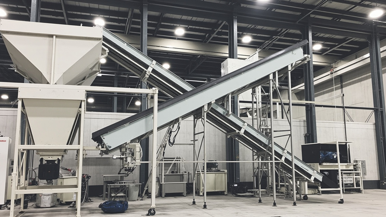
Types of Hopper Elevators: Belt, Vibratory, and Centrifugal
Hopper elevators fall into three primary categories based on their elevation mechanism. Each type has distinct advantages, limitations, and optimal part families. Selecting the wrong type is a common cause of chronic feeding problems that are mistakenly blamed on the bowl feeder.
Belt elevators use a continuous belt with cleats, pockets, or magnetic attachments to lift parts from the hopper bottom to the discharge chute. Belt elevators are the most versatile type, handling a wide range of part sizes, shapes, and materials. They excel with oily or sticky parts that do not flow freely, heavy parts that require positive mechanical lifting, and applications where precise discharge timing is needed. Belt speed is adjustable to match downstream demand. The primary limitations are belt wear (especially with abrasive parts) and the potential for part marking from belt contact.
Vibratory hopper elevators use an inclined vibratory tray or spiral track to move parts upward through vibration, similar in principle to a vibratory bowl feeder but oriented vertically. These elevators are gentle on parts, produce minimal noise, and have no belts or chains to wear. They work best with dry, free-flowing parts that respond well to vibratory conveying. Vibratory elevators are often the most compact option and integrate aesthetically with vibratory bowl feeders as part of a unified system. Limitations include reduced effectiveness with oily or adhesive parts and lower lifting capacity for very heavy components.
Stepped elevators use a series of mechanical steps, similar to a step feeder, to lift parts from the hopper in discrete increments. These are the gentlest option for delicate or coated parts and are often used when part surface protection is paramount. Step elevators are mechanically more complex than belt or vibratory types but offer the lowest risk of part damage. They are typically slower than belt elevators and are best suited to moderate volumes of sensitive components.
Huben Automation offers all three hopper elevator types and frequently combines them with our vibratory bowl feeder systems as integrated packages. The selection is always based on part testing rather than assumptions.
Hopper Sizing Calculations: From Runtime to Capacity
The correct starting point for hopper sizing is not capacity in liters — it is required unattended runtime in minutes or hours. Once the runtime target is established, capacity follows from part geometry, bulk density, and line consumption rate.
The fundamental sizing equation is:
Hopper capacity (parts) = Line consumption (parts/minute) × Target runtime (minutes) × Safety factor
The safety factor typically ranges from 1.2 to 1.5, accounting for variations in part bulk density, non-uniform filling, and the fact that the last 10–20% of hopper volume is often inaccessible to the elevator mechanism. For critical applications running unmanned shifts, a safety factor of 1.5 is prudent.
Converting part count to hopper volume requires the part bulk density, which is always less than the material density due to interstitial air gaps. Bulk density is best determined experimentally by filling a known volume with parts and weighing, but approximate values can be used for initial estimates:
| Part type | Typical bulk density (kg/L) | Parts per liter (typical) | Practical hopper range |
|---|---|---|---|
| Small fasteners (M3–M6 screws) | 0.8–1.2 | 200–500 | 20–50 L |
| Medium stampings and brackets | 0.5–0.9 | 50–150 | 30–80 L |
| Large housings and covers | 0.3–0.6 | 10–40 | 50–100 L+ |
| Plastic injection molded parts | 0.2–0.5 | 30–100 | 30–80 L |
| Delicate coated metal parts | 0.4–0.7 | 20–60 | 10–50 L |
| Cylindrical rollers and pins | 0.6–1.0 | 100–300 | 20–60 L |
These values are starting points only. The actual bulk density of your specific part depends on geometry, surface finish, and whether parts tend to nest or bridge. Huben always recommends physical measurement with production parts before finalizing hopper volume.
There is also a practical upper limit to hopper size. Very large hoppers increase footprint, raise loading height beyond ergonomic limits, and may require mechanical lifting aids for refill. A 100 L hopper filled with steel parts can weigh over 80 kg — difficult and potentially unsafe to load manually. For very large capacities, consider a bulk bag unloader, drum tipper, or vacuum conveyor as the primary supply, with the hopper acting as a buffer rather than the main storage.
Level Control Systems and Refill Logic
The hopper elevator must do more than store parts — it must deliver them to the bowl at the right rate and the right time. This is the function of the level control system, which monitors bowl fill level and activates the elevator when replenishment is needed.
Three sensor technologies are commonly used for level detection:
Photoelectric sensors use a light beam that is interrupted by parts in the bowl. They are non-contact, inexpensive, and reliable for most part types. Through-beam sensors provide the most consistent detection but require alignment. Reflective sensors are easier to install but may give false readings with shiny or transparent parts.
Capacitive sensors detect the presence of parts by measuring changes in capacitance. They work through non-metallic bowl walls, allowing hidden installation, and are unaffected by part color or transparency. Capacitive sensors are ideal for cleanroom applications where external sensors would create contamination risks. Limitations include sensitivity to moisture and the need for calibration to the specific part material.
Weight-based systems measure the mass of parts in the bowl using load cells. These are the most accurate level measurement method and are immune to part geometry or optical properties. However, they are more expensive and require mechanical isolation from vibration to prevent false readings. Weight systems are typically reserved for high-precision or regulated applications.
The control logic is as important as the sensor selection. A simple on/off control — elevator runs when the level is low, stops when full — creates cyclic overfill and underfill. Better control uses a hysteresis band: the elevator starts when the level drops to the lower setpoint and continues until the upper setpoint is reached. The gap between setpoints should be wide enough to prevent rapid cycling but narrow enough to maintain stable bowl fill.
Even with hysteresis, large refill events can overwhelm the bowl. The best practice is to run the elevator at a controlled rate — either by adjusting belt speed, using a short refill pulse, or adding a metering gate — so parts enter the bowl gradually rather than in a single dump. This protects orientation tooling and prevents the recirculation that occurs when the bowl is overfilled.
Integration with Vibratory Bowl Feeders
The hopper elevator and vibratory bowl feeder are a single system, not two separate machines. Their integration determines whether the feeding line runs smoothly or chronically underperforms.
Discharge chute design: The chute that transfers parts from the elevator to the bowl must be sized and angled correctly. Too steep an angle causes parts to tumble and arrive in random orientations. Too shallow an angle causes parts to stall or bridge. The chute should terminate at the bowl center or slightly above the expected part bed level, not drop parts from a height that creates impact damage or scattering.
Vibration isolation: The hopper elevator must be mounted independently from the vibratory bowl feeder. If the two units share a common frame, vibration from the bowl will transmit to the hopper, causing premature wear and potentially causing parts to migrate unpredictably within the hopper. Huben systems use separate frames with flexible connections at the discharge chute.
Electrical coordination: The elevator motor or vibratory drive should be controlled by the bowl feeder's level sensors, not run continuously. Running the elevator continuously wastes energy, increases wear, and creates unnecessary noise. The control system should also include a timeout alarm: if the elevator runs for longer than expected without reaching the full setpoint, an alarm indicates a jam, empty supply, or mechanical failure.
Refill timing: The ideal refill strategy keeps the bowl between one-third and one-half full. At this level, parts have sufficient room to orient without excessive recirculation, and the bowl drive is not overloaded. Refilling should begin before the bowl reaches a critically low level that would cause starvation of the downstream process.
For more guidance on bowl feeder capacity and fill level optimization, see our capacity calculation guide.
Common Integration Problems and Solutions
Even with correctly sized components, integration issues can degrade system performance. The following problems occur frequently enough that they should be checked on every installation:
Problem: Bowl floods after refill. The elevator delivers too many parts too quickly, overwhelming the bowl's orientation capacity. Parts pile up at tooling points and jam. Solution: Reduce elevator speed, add a metering gate, or adjust the level sensor setpoints to trigger more frequent, smaller refills.
Problem: Bowl starves despite full hopper. Parts are not transferring reliably from hopper to elevator, or the elevator is not discharging into the bowl correctly. Solution: Check for bridging in the hopper (especially with interlocking parts), verify elevator mechanism function, and confirm that the discharge chute is clear and correctly positioned.
Problem: Parts are damaged during transfer. Parts collide with each other or with hard surfaces during elevation or discharge. Solution: Add cushioning to the discharge chute, reduce elevator speed, or switch to a gentler elevator type (vibratory instead of belt, or stepped instead of vibratory).
Problem: Excessive noise from hopper. The elevator mechanism, part movement in the hopper, or impact at discharge creates noise that adds to the already significant sound level of the vibratory bowl. Solution: Add acoustic lining to the hopper walls, use a vibratory or stepped elevator instead of belt, and ensure the discharge chute has a soft landing zone.
Problem: Operator cannot load hopper safely. The hopper inlet is too high, too small, or awkwardly positioned. Operators resort to unsafe lifting or pouring methods. Solution: Design the hopper inlet height below 1.2 meters for manual loading, provide a wide inlet with a funnel or guide, and consider a drum tipper or vacuum loader for heavy or bulky refill.
Practical Sizing Example
Consider an automotive assembly line consuming M6 bolts at 120 parts per minute, running two 8-hour shifts per day. The target is 4 hours of unattended runtime per shift to cover operator breaks and changeovers.
Required parts capacity = 120 ppm × 240 minutes × 1.3 safety factor = 37,440 parts.
M6 steel bolts have a bulk density of approximately 1.0 kg/L and about 350 parts per liter when randomly packed.
Required hopper volume = 37,440 ÷ 350 = 107 liters.
This exceeds the practical manual loading limit. The solution is to use a 50 L hopper with automatic refill from a bulk supply bin via a vacuum conveyor or drum tipper. The 50 L hopper provides approximately 2 hours of runtime, and the automatic refill cycles every 2 hours without operator intervention.
Alternatively, if automatic refill is not feasible, a 100 L hopper with a low loading height and wide mouth could be used, with parts supplied in smaller containers that operators can lift safely. The key point is that sizing must consider both the mathematical capacity and the practical constraints of the production environment.
Maintenance Schedule for Hopper Elevators
Hopper elevators require less maintenance than vibratory bowl feeders but should not be neglected. A well-maintained hopper ensures consistent bowl supply and prevents the chronic problems that are often misdiagnosed as bowl feeder issues.
- Daily: Check bowl level sensor function, verify hopper has adequate supply, listen for unusual noises from elevator mechanism
- Weekly: Inspect belt or chain tension (belt elevators), clean hopper interior of dust and debris, check discharge chute for blockages
- Monthly: Lubricate bearings and drive components, inspect sensor alignment and cleanliness, verify control setpoints
- Quarterly: Replace wear items such as belt cleats or vibratory tray liners, check electrical connections for vibration loosening
- Annually: Full mechanical inspection, replacement of belts or springs as preventive maintenance, calibration of level sensors
Frequently Asked Questions About Hopper Elevators
How do I determine the right hopper size for my application?
Start with required unattended runtime, not liters. Calculate line consumption in parts per minute, multiply by target runtime in minutes, and apply a safety factor of 1.2 to 1.5. Convert to volume using the actual bulk density of your parts, measured by filling a known container. Consider practical limits: hoppers over 50 liters may be difficult to load manually, and very large hoppers increase footprint and cost. Huben provides a sizing worksheet with every quotation to ensure the hopper matches your runtime target and loading constraints.
Which hopper elevator type is best for oily or sticky parts?
Belt elevators are generally the best choice for oily or sticky parts because the positive mechanical lifting action overcomes adhesion and friction that would stall vibratory or step mechanisms. The belt cleats physically engage and lift parts regardless of surface condition. However, oily parts may contaminate the belt over time, requiring periodic cleaning or replacement. For severely oily parts, consider a vibratory hopper with a perforated tray that allows oil to drain, combined with a belt elevator for the lifting stage. Huben tests parts with actual production lubricants to verify elevator performance.
What type of level sensor works best with vibratory bowl feeders?
Photoelectric sensors are the most common and cost-effective choice for general industrial applications. Capacitive sensors are preferred for cleanrooms, transparent parts, or when the sensor must be hidden behind a non-metallic bowl wall. Weight-based systems provide the highest accuracy but at higher cost and complexity. The best sensor is the one that works reliably with your specific part geometry and production environment. Huben typically supplies photoelectric sensors as standard and offers capacitive or weight-based upgrades for challenging applications.
Can a hopper elevator reduce overall feeding system noise?
The hopper itself does not reduce bowl noise, but the choice of elevator type affects the total system noise level. Vibratory and stepped elevators are quieter than belt elevators. A well-designed hopper can also reduce part-on-part noise by maintaining consistent bowl fill — an underfilled bowl allows parts to rattle and collide more than a properly filled one. For comprehensive noise reduction strategies, see our vibratory feeder noise reduction guide.
Can one hopper elevator supply multiple bowl feeders?
Yes, but with careful design. A single large hopper can feed multiple bowls through a distribution chute or splitter, but each bowl must have independent level control. Without individual control, one bowl may be overfilled while another starves. The distribution system must also ensure equal part flow to each bowl, which can be challenging with parts that vary in weight or shape. Huben has designed centralized hopper systems feeding up to four bowl feeders for high-volume applications, but single-hopper-single-bowl remains the most reliable configuration.
How much does a hopper elevator add to system cost?
A hopper elevator typically adds 15% to 35% to the total feeding system cost, depending on type and capacity. Belt elevators are generally the least expensive; stepped elevators the most. While this may seem significant, the payback period is usually short when operator time savings and reduced downtime are considered. A hopper that eliminates just two manual refills per shift can save hundreds of operator hours annually. Huben includes hopper sizing and integration in every system quotation to ensure the complete solution is optimized for your production economics.
Conclusion: Integrating Hopper Elevators for Reliable Production
The hopper elevator is not an accessory — it is an integral component of the feeding system that determines uptime, labor efficiency, and bowl performance. Proper sizing based on runtime requirements, correct type selection for the part material, and intelligent level control are essential for reliable unattended operation.
Huben Automation designs hopper elevators as part of complete feeding systems, not as standalone products. Every hopper is sized using your actual part samples and production targets, integrated with the bowl feeder for optimal refill behavior, and tested before shipment to verify unattended runtime.
If your current feeding line requires too much operator attention, suffers from inconsistent bowl fill, or needs to run unmanned shifts, a properly engineered hopper elevator may be the solution. Contact Huben Automation to discuss your runtime requirements and part characteristics. With ISO 9001 certification, 20+ years of experience, and factory-direct pricing, we deliver hopper systems that keep your production line running.
¿Listo para automatizar su producción?
Obtenga una consulta gratuita y un presupuesto detallado en 12 horas por parte de nuestro equipo de ingeniería.


