Ausrichtungsprobleme von Zuführschüsseln: Ursachen & Lösungen
Wenn Teile sich weigern sich zu orientieren: Die wahren Kosten von Orientierungsversagen
Ein Vibrationsrüttelwendelförderer, der Teile in der falschen Orientierung liefert, ist schlimmer als ein Förderer, der überhaupt nicht läuft. Zumindest löst ein gestoppter Förderer sofort einen Alarm aus. Ein Förderer mit schlechter Orientierungsausbeute füllt downstream Geräte stillschweigend mit falsch ausgerichteten Teilen, was Montagefehler, Robotergreiferfehler, Qualitätsdurchschlupf und in den schlimmsten Fällen Produktrückrufe verursacht. Die Kosten einer einzelnen falschen Orientierung vervielfachen sich, wenn das Teil durch nachgelagerte Bearbeitungen fortschreitet, akkumuliert Wert, bevor es verworfen wird.
Orientierungsprobleme gehören auch zu den technisch herausforderndsten Fördererproblemen bei der Diagnose. Dieselbe Rüttel, die gestern perfekt orientiert hat, kann heute aufgrund von Teilvariationen, Werkzeugverschleiß oder Umgebungsveränderungen versagen, die bei flüchtiger Inspektion unsichtbar sind. Die Grundursache kann im Rütteldesign, der Werkzeuggeometrie, den Vibrationsparametern, dem Teil selbst oder in einer Wechselwirkung zwischen allen vier Faktoren liegen. Ohne strukturierte Diagnosemethoden können Wartungsteams Tage damit verbringen, Symptome zu beheben, während die zugrunde liegende Ursache unangetastet bleibt.
Dieses Handbuch bietet einen systematischen Rahmen zur Diagnose und Lösung von Rüttelförderer-Orientierungsproblemen. Es behandelt die mechanischen Prinzipien der Orientierung, häufige Fehlermodi, Root-Cause-Analysetechniken und korrigierende Maßnahmen, die durch Huben Automations zwei Jahrzehnte Fördererdesign und Feldserviceerfahrung validiert wurden. Ob Sie einen neuen Förderer in Betrieb nehmen, ein chronisches Problem analysieren oder bewerten, ob eine bestehende Rüttel an ein neues Teil angepasst werden kann - die hier beschriebenen Prinzipien helfen Ihnen, Orientierungsausbeuten von über 99% zu erreichen und aufrechtzuerhalten.
Wie die Rüttelförderer-Orientierung tatsächlich funktioniert
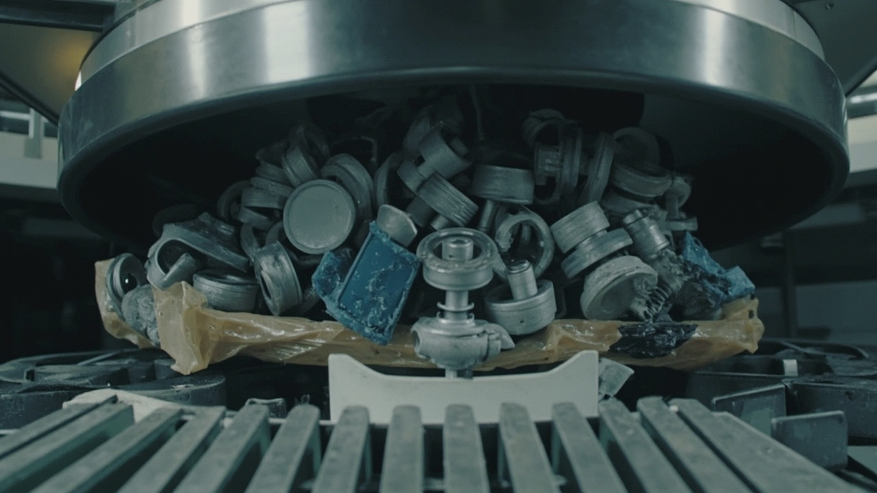
Die Orientierung in einem Vibrationsrüttelförderer ist kein einzelnes Ereignis, sondern ein sequentieller Prozess. Teile treten in zufälligen Lagen vom Rüttelzentrum in die Spiralschiene ein. Während sie aufwärts wandern, treffen sie auf eine Reihe von Werkzeugelementen - Selektoren, Abstreifer, Nuten, Aussparungen und Luftdüsen - die jeweils entwickelt wurden, um bestimmte falsche Orientierungen abzulehnen, während die korrekte Orientierung passieren darf. Bis ein Teil den Auswurfpunkt erreicht, sollte es mehrere Ablehnungsstufen überlebt haben, wodurch nur die gewünschte Lage übrig bleibt.
Jedes Orientierungselement funktioniert durch Ausnutzen eines geometrischen Unterschieds zwischen korrekter und inkorrekter Orientierung. Eine Selektor Klinge kann einen Maßunterschied nutzen: Teile, die aufrecht stehen, sind höher als flachliegende Teile, sodass eine Klinge auf mittlerer Höhe die hohe Orientierung umstößt, während die flache Orientierung darunter passiert. Eine Nut kann einen Schwerpunktunterschied nutzen: Teile mit dem schweren Ende nach unten bleiben in einer Nut stabil, während Teile mit dem schweren Ende nach oben umkippen. Eine Luftdüse kann einen Oberflächenunterschied nutzen: Eine breite Fläche bietet ein größeres Ziel für einen Luftstoß als eine schmale Kante, wodurch der Stoß Teile in falscher Lage wegblasen kann.
Die kritische Erkenntnis ist, dass Orientierung von Unterscheidbarkeit abhängt - der geometrische Unterschied zwischen korrekter und inkorrekter Orientierung muss groß genug sein, um von mechanischen Elementen zuverlässig erkannt und bearbeitet zu werden. Wenn der Unterschied subtil ist, wird die Orientierungsausbeute unabhängig von der Werkzeugqualität marginal sein. Wenn der Unterschied groß ist, aber das Werkzeug verschlissen oder falsch eingestellt ist, wird die Ausbeute mit der Zeit abnehmen. Sowohl Design als auch Wartung sind unerlässlich.
Huben Automation entwickelt Orientierungswerkzeuge unter Verwendung eines dreistufigen Verifizierungsprozesses: CAD-Simulation der Teilgeometrie, physische Prototypenherstellung mit Musterteilen und statistische Validierung mit Produktionschargen. Diese Methodik erkennt Orientierungsprobleme, bevor der Förderer versandt wird, und eliminiert das Ausprobieren, das weniger rigorose Designansätze charakterisiert.
Häufige Orientierungsprobleme und ihre Merkmale
Orientierungsfehler erzeugen charakteristische Muster, die ihre Ursache offenbaren. Das Erlernen, diese Signaturen zu lesen, beschleunigt die Diagnose erheblich.
Zufällige Orientierung am Auswurf: Teile verlassen die Anlage in mehreren Lagen ohne dominierenden Fehlermodus. Dies zeigt typischerweise ein vollständiges Versagen der primären Orientierstation an - ein Selektor, der grob fehlausgerichtet, fehlend oder über seine Funktion hinaus verschlissen ist. Alternativ kann die Vibrationsamplitude so hoch sein, dass Teile über alle Werkzeuge hinwegspringen, ohne sie zu berühren. Überprüfen Sie zuerst das am weitesten upstream gelegene Orientierungselement; wenn es nicht funktioniert, erhalten downstream Elemente einen bereits randomisierten Teilestrom.
Konsistente einzelne falsche Orientierung: Die meisten Teile verlassen die Anlage in einer bestimmten inkorrekten Lage. Dies zeigt an, dass das Orientierungselement, das entwickelt wurde, um diese bestimmte Lage abzulehnen, versagt. Wenn beispielsweise Teile aufrecht stehend austreten, obwohl sie flach liegen sollten, ist der Höhenselektor, der aufrechte Teile umstoßen sollte, entweder zu hoch (berührt sie nicht) oder verschlissen (ermöglicht ihnen das Passieren). Die Lösung ist gezielte Einstellung oder Ersetzung des spezifisch ausgefallenen Elements.
Über die Zeit abnehmende Orientierungsausbeute: Die Ausbeute beginnt akzeptabel, verschlechtert sich aber über Tage oder Wochen allmählich. Dies ist das Kennzeichen von Werkzeugverschleiß oder schleichender Verschiebung. Vibration lockert Befestigungselemente, verschleißt Selektorkanten und verändert Federcharakteristiken. Die Degradationsrate deutet auf den Schweregrad hin: schnelle Degradation deutet auf lose Befestigungselemente oder weiches Werkzeugmaterial hin; langsame Degradation deutet auf normalen Verschleiß hin, der geplante Ersatz erfordert.
Mit der Rüttelfüllung variierende Orientierungsausbeute: Die Ausbeute ist bei niedriger Füllung gut, aber schlecht bei hoher Füllung, oder umgekehrt. Dies zeigt eine Wechselwirkung zwischen Teiledichte und Orientierungsdynamik an. Bei hoher Füllung können Teile auf der Schiene gestapelt sein und sich gegenseitig vor Selektoren abschirmen. Bei niedriger Füllung haben Teile möglicherweise nicht genug Impuls, um mit dem Werkzeug in Kontakt zu kommen. Die Lösung umfasst normalerweise die Anpassung des Füllstandsregelungssystems, um konsistente Rüttelfüllung aufrechtzuerhalten.
Mit der Teilcharge variierende Orientierungsausbeute: Die Ausbeute verschlechtert sich sofort nach einer neuen Teilelieferung und verbessert sich dann, wenn die vorherige Charge zurückkommt. Dies ist ein eindeutiger Beweis für Teilvariation. Messen Sie Abmessungen, Gewicht und Oberflächenfinish der problematischen Charge im Vergleich zur ursprünglichen Spezifikation. Selbst Änderungen innerhalb der Zeichnungstoleranz können die Orientierung beeinflussen, wenn das Werkzeug für den Mittelwert statt für den gesamten Toleranzbereich ausgelegt wurde.
| Fehlersignatur | Wahrscheinlichste Ursache | Erster Diagnoseschritt | Typische Lösung |
|---|---|---|---|
| Zufällige Orientierungen | Primäres Selektorversagen oder übermäßige Amplitude | Inspizieren Sie upstream Selektor; messen Sie Amplitude | Selektor neu ausrichten oder ersetzen; Amplitude reduzieren |
| Einzelne konsistente falsche Orientierung | Spezifischer Selektor verschlissen oder fehleingestellt | Identifizieren Sie, welcher Selektor diese Lage ablehnen sollte | Den ausgefallenen Selektor einstellen oder ersetzen |
| Ausbeute verschlechtert sich über Zeit | Werkzeugverschleiß oder Lockern von Befestigungselementen | Werkzeugkanten inspizieren; Anzugsdrehmoment prüfen | Verschlissenes Werkzeug ersetzen; Gewindesicherung auftragen |
| Ausbeute variiert mit Rüttelfüllung | Teiledichte-Wechselwirkung mit Werkzeug | Bei mehreren Füllständen testen | Füllstandsregelung anpassen; Mengendosierventil hinzufügen |
| Ausbeute variiert mit Teilcharge | Teilmaßliche oder Materialvariation | Teile aus guten und schlechten Chargen messen | Werkzeug für Toleranzbereich neu gestalten; Lieferanten qualifizieren |
| Ausbeute sinkt nach Wartung | Werkzeug während der Wartung gestört | Aktuelle Werkzeugpositionen mit Baseline-Fotos vergleichen | Originale Werkzeugpositionen wiederherstellen; Einrichtung dokumentieren |
Werkzeugdesign-Probleme: Wenn die Grundlage falsch ist
Wenn Orientierungsprobleme trotz korrekter Einstellung und Wartung bestehen bleiben, kann die Grundursache im ursprünglichen Werkzeugdesign liegen. Einige Teilgeometrien sind von Natur aus schwierig zu orientieren, und Werkzeuge, die für eine Teilfamilie funktionieren, können für eine andere grundlegend ungeeignet sein.
Unzureichende geometrische Unterscheidbarkeit: Der häufigste Designfehler ist der Versuch, Teile zu orientieren, die keine ausreichenden geometrischen Unterschiede zwischen ihren stabilen Lagen aufweisen. Ein Teil, das nahezu symmetrisch ist - ein Quader mit leicht unterschiedlichen Flächenabmessungen oder ein Zylinder mit minimalen Endenmerkmalen - bietet möglicherweise nicht genug Unterschied, den mechanische Selektoren ausnutzen können. In diesen Fällen hat die Orientierungsausbeute eine theoretische Obergrenze unter 100%, unabhängig von der Werkzeugverfeinerung. Lösungen umfassen das Hinzufügen einer bewussten Asymmetrie zum Teiledesign (in Zusammenarbeit mit dem Konstruktionsteam des Kunden), die Verwendung von Visionsystemen zur Orientierungsverifizierung oder die Akzeptanz einer niedrigeren Ausbeute mit manueller Sortierung.
Selektorgeometrie-Fehler: Eine Selektorklinge muss das Teil am richtigen Punkt und Winkel kontaktieren, um die gewünschte Neuorientierung zu erzeugen. Wenn der Klingenwinkel zu flach ist, rutscht sie unter dem Teil hindurch, anstatt es zu schieben. Wenn er zu steil ist, klemmt sie das Teil gegen die Schienenwand. Wenn der Kontaktpunkt falsch ist, kann sie das Teil in eine dritte, gleichermaßen falsche Orientierung drehen, anstatt die gewünschte. Huben verwendet CAD-Simulation und Rapid Prototyping, um die Selektorgeometrie zu verifizieren, bevor Produktionswerkzeuge gefertigt werden.
Schienengeometrie-Mismatch: Die Spiralschiene muss zur Kontaktgeometrie des Teils passen. Eine Schiene, die zu breit ist, ermöglicht es Teilen zu taumeln und die Orientierung nach dem Passieren von Selektoren zu ändern. Eine Schiene mit unzureichender Seitenwandhöhe ermöglicht es Teilen, über die Kante zu kippen. Die Stufenhöhe zwischen Spiraldurchgängen muss die Teiledicke aufnehmen, ohne hängen zu bleiben. Diese geometrischen Beziehungen werden während des Rütteldesigns festgelegt und können nicht durch Einstellung korrigiert werden - sie erfordern Rüttelmodifikation oder -austausch.
Luftdüsen-Integrationsfehler: Wenn Luftdüsen für Orientierung oder Wegblasen verwendet werden, müssen ihre Position, ihr Winkel, ihr Druck und ihre Timing präzise koordiniert sein. Eine leicht fehlgerichtete Düse kann das Teil möglicherweise vollständig verfehlen. Eine Düse mit unzureichendem Druck schafft es nicht, die Trägheitsstabilität des Teils zu überwinden. Eine Düse, die zum falschen Zeitpunkt im Vibrationszyklus auslöst, verfehlt das Teil, wenn es hüpft. Huben integriert das Luftdüsendesign in die Gesamtwerkzeugstrategie, anstatt Düsen nachträglich hinzuzufügen.
Vibrationseinstellungen: Die versteckte Variable bei der Orientierung
Vibrationsparameter haben einen tiefgreifenden, aber oft unterschätzten Einfluss auf die Orientierungsausbeute. Teile müssen genug Energie haben, um mit Werkzeugelementen in Kontakt zu kommen, aber nicht so viel, dass sie darüber hinweghüpfen oder durch sie hindurchgehen. Das optimale Vibrationsfenster ist enger, als viele Bediener es erkennen.
Amplitudeneffekte: Niedrige Amplitude führt dazu, dass Teile gleiten statt hüpfen, was verhindert, dass sie Schienenstufen erklimmen oder sich drehen, wenn sie von Selektoren kontaktiert werden. Hohe Amplitude führt dazu, dass Teile klare über Werkzeugelemente hinweghüpfen oder so hart gegen die Schienenwand schlagen, dass sie in falsche Orientierungen zurückprallen. Die optimale Amplitude ist typischerweise der niedrigste Wert, der zuverlässige Teilbewegung erzeugt - ein kontraintuitives Ergebnis für Bediener, die mehr Vibration mit besserem Fördern assoziieren.
Frequenzeffekte: Die Frequenz bestimmt, wie viele Vibrationszyklen pro Zeiteinheit auftreten und somit wie viele Gelegenheiten das Teil hat, mit dem Werkzeug zu interagieren. Bei sehr niedrigen Frequenzen bewegen sich Teile in großen Hüpfen, die Selektoren überspringen können. Bei sehr hohen Frequenzen können Teile fluidisieren und wie eine Flüssigkeit fließen, was die individuelle Orientierungskontrolle verliert. Die Resonanzfrequenz des Förderers - wo der mechanische Wirkungsgrad am höchsten ist - ist normalerweise auch die beste Orientierungsfrequenz, aber dies sollte mit tatsächlichen Teilen verifiziert werden.
Wellenformeffekte: Moderne Controller können die Vibrationswellenform von sinusförmig bis zu komplexeren Mustern variieren. Einige Teile orientieren sich besser mit scharfen Beschleunigungsimpulsen, die Rotation übertragen, während andere gleichmäßige sinusförmige Bewegung benötigen, um Taumeln zu verhindern. Experimentieren mit Wellenformeinstellungen kann die Orientierungsausbeute für schwierige Teile verbessern, ohne mechanische Änderungen vorzunehmen.
Rüttellast-Wechselwirkung: Die effektive Vibration, die ein Teil auf der Schiene erfährt, hängt davon ab, wie viele andere Teile sich in der Rüttel befinden. Ein schwerer Teileteppich dämpft die Schwingungsübertragung auf die Schiene. Eine unterfüllte Rüttel kann übermäßige Schienenvibration verursachen, da der Antrieb in eine leichte Last arbeitet. Die Aufrechterhaltung einer konsistenten Rüttelfüllung durch ordnungsgemäße Behälter-Füllstandsregelung ist für stabile Orientierung unerlässlich. Für mehr zu diesem Thema lesen Sie unseren Behälteraufzug-Integrationsleitfaden.
Teilgeometrie und Fertigungsvariation
Das Teil selbst ist die Variable, die am seltensten zuletzt beschuldigt wird und zuerst untersucht werden sollte. Ein Förderer kann nicht orientieren, was nicht orientierbar ist, und Werkzeuge, die für eine Teilrevision entwickelt wurden, können für eine andere versagen.
Dimensions-Toleranz-Stack-Up: Orientierungswerkzeuge werden um Nenn-Teilabmessungen mit Spielraum für Toleranzvariation herum entwickelt. Wenn mehrere Abmessungen gleichzeitig variieren - Länge, Breite, Höhe und Merkmalposition - kann die statistische Kombination Teile erzeugen, die außerhalb des Annahmefensters des Werkzeugs liegen, obwohl jede einzelne Abmessung innerhalb der Spezifikation liegt. Dies ist besonders problematisch für spritzgegossene Teile, bei denen Schrumpfung mit Wandstärke und Abkühlrate variiert.
Oberflächenfinish-Änderungen: Ein Teil mit glatter, reibungsarmer Oberfläche verhält sich auf einer Vibrationsschiene anders als dasselbe Teil mit texturierter oder matter Oberfläche. Reibung beeinflusst Gleiten, Hüpfen und den Kontakt mit Selektoren. Eine Lieferantenänderung von poliertem zu sandgestrahltem Finish kann die Orientierungsausbeute verschlechtern, selbst wenn alle Abmessungen identisch bleiben.
Grat, Bart und Angussreste:
Formteile und Gussteile tragen oft kleine Vorsprünge, die innerhalb der Spezifikation, aber groß genug sind, um an Werkzeugkanten hängen zu bleiben. Ein 0,3 mm Grat an einer sonst glatten Kante kann sich in einen Selektorspalt verkeilen und konsistente Blockierungen an einer bestimmten Stelle verursachen. Angussreste an zylindrischen Teilen können Rollen verhindern und die natürlichen stabilen Orientierungen ändern.Materialeigenschaftsvariation: Dichteänderungen beeinflussen, wie Teile auf Vibration und Luftdüsen reagieren. Ein Teil mit dichterem Füllstoff ist schwerer und stabiler in seiner bevorzugten Orientierung, aber härter für Luftdüsen wegzublasen. Feuchtigkeitsaufnahme in hygroskopischen Kunststoffen verändert sowohl Gewicht als auch Oberflächenreibung. Diese Eigenschaften werden selten so eng kontrolliert wie Abmessungen, können aber das Orientierungsverhalten erheblich beeinflussen.
Wenn Teilvariation vermutet wird, ist das Diagnoseprotokoll klar: Messen und vergleichen Sie gute und schlechte Teile über alle relevanten Eigenschaften, nicht nur Abmessungen. Huben pflegt eine Bibliothek von Teilmessdaten aus Tausenden von Förderprojekten und kann oft die kritische Eigenschaft aus der Fehlersignatur identifizieren.
Systematisches Diagnoseprotokoll
Wenn Sie mit einem Orientierungsproblem konfrontiert sind, befolgen Sie dieses Protokoll, um zufällige Einstellungen und verschwendete Zeit zu vermeiden:
Schritt 1: Basisdaten etablieren. Bevor Sie irgendetwas berühren, erfassen Sie die aktuelle Orientierungsausbeute über eine statistisch signifikante Stichprobe - minimum 200 Teile. Dokumentieren Sie den Rüttelfüllstand, die Vibrationseinstellungen, die Teilchargennummer und die Umgebungsbedingungen. Machen Sie Fotos aller Werkzeugpositionen als Referenz.
Schritt 2: Den Fehlermodus identifizieren. Sortieren Sie die falsch orientierten Teile nach ihrer tatsächlichen Lage. Gibt es eine dominante falsche Orientierung oder viele? Ändert sich die falsche Orientierung mit der Zeit oder bleibt sie konsistent? Der Fehlermodus zeigt auf die ausgefallene Werkzeugstufe.
Schritt 3: Werkzeug mechanisch inspizieren. Überprüfen Sie alle Befestigungselemente auf Anzugsdrehmoment. Messen Sie Werkzeugspiele mit Fühlerlehren gegen die Designspezifikation. Inspizieren Sie Kanten unter Vergrößerung auf Verschleiß. Verifizieren Sie Luftdüsndruck und -ausrichtung. Suchen Sie nach Fremdmaterial, gebrochenen Werkzeugfragmenten oder Beschichtungsschäden.
Schritt 4: Vibrationsparameter verifizieren. Bestätigen Sie, dass die Betriebsfrequenz bei oder nahe der Resonanz liegt. Verifizieren Sie, dass die Amplitude innerhalb des Designbereichs liegt. Überprüfen Sie, dass der Controller nicht in einem Fehler- oder Grenzzustand ist. Messen Sie die tatsächliche Vibration mit einem Beschleunigungssensor, wenn verfügbar.
Schritt 5: Mit bekannten guten Teilen testen. Wenn möglich, fahren Sie Teile aus einer Charge mit historisch guter Orientierungsausbeute. Wenn sich die Ausbeute verbessert, liegt das Problem in der Teilvariation. Wenn die Ausbeute schlecht bleibt, liegt das Problem im Förderer.
Schritt 6: Machen Sie jeweils eine Änderung. Stellen Sie einen Parameter ein, ersetzen Sie eine Komponente oder modifizieren Sie ein Werkzeugelement. Testen Sie die Orientierungsausbeute nach jeder Änderung. Mehrere gleichzeitige Änderungen machen es unmöglich zu bestimmen, welche Maßnahme wirksam war.
Schritt 7: Stabilität über Zeit verifizieren. Eine Lösung, die fünf Minuten funktioniert, funktioniert möglicherweise nicht fünf Stunden. Fahren Sie den Förderer für mindestens einen vollständigen Produktionszyklus, bevor Sie Erfolg erklären. Überwachen Sie auf schleichende Verschlechterung, die Verschleiß oder thermische Drift anzeigt.
Bewährte Lösungen und Einstellungen
Basierend auf der Diagnose wenden Sie die appropriate Lösung aus dieser Hierarchie an:
Level 1: Kostenlose betriebliche Einstellungen
- Rüttelfüllstand auf ein Drittel bis die Hälfte des Volumens optimieren
- Amplitude auf das minimale effektive Niveau reduzieren
- Frequenz zu Resonanz verifizieren und einstellen
- Schiene und Werkzeug von Verunreinigungen reinigen
- Luftdüsndruck und -ausrichtung verifizieren
Level 2: Günstige mechanische Korrekturen
- Alle Befestigungselemente auf Spezifikation anziehen; Gewindesicherungsmittel auftragen
- Werkzeugspiele mit Fühlerlehren einstellen
- Verschlissene Selektorklingen oder Abstreifer ersetzen
- Anti-Verschachtelungs-Elemente im Rüttelzentrum hinzufügen oder einstellen
- Mengendosierventil zur Schienenbelastungskontrolle installieren
Level 3: Komponentenersatz und Upgrades
- Federpaket ersetzen, um Abstimmung wiederherzustellen
- Verschlissene Schienenbeschichtung ersetzen
- Auf Controller mit variabler Frequenz mit feinerer Einstellung upgraden
- Zusätzliche Orientierungsstufe für marginale Geometrien installieren
- Visionsverifizierungsstation downstream des Förderers hinzufügen
Level 4: Designmodifikationen
- Werkzeug für geänderte Teilgeometrie neu gestalten
- Rüttelschienengeometrie für bessere Teilestabilität modifizieren
- Teil neu gestalten, um geometrische Unterscheidbarkeit zu erhöhen
- Rüttelförderer durch alternative Technologie ersetzen (Stufenförderer, flexibler Förderer)
Die meisten chronischen Orientierungsprobleme werden auf Level 1 oder 2 gelöst. Der Schlüssel ist systematische Diagnose, die die wahre Ursache identifiziert, anstatt Symptome zu behandeln.
Häufig gestellte Fragen zu Orientierungsproblemen
Welche Orientierungsausbeute sollte ich von einem Vibrationsrüttelförderer erwarten?
Für Teile mit guter geometrischer Unterscheidbarkeit und ordnungsgemäßem Werkzeugdesign sollte die Orientierungsausbeute unter normalen Betriebsbedingungen 99% überschreiten. Ausbeuten von 99,5% oder höher sind mit gut gewarteten Systemen erreichbar. Wenn Ihre Anwendung 100% korrekte Orientierung erfordert, ist ein Vibrationsrüttelförderer allein unzureichend - Sie benötigen eine downstream Verifizierungs- und Ablehnungsstation, wie ein Visionssystem oder mechanisches Tor, um die unvermeidliche gelegentliche Fehlorientierung abzufangen. Huben gestaltet integrierte Systeme mit Verifizierungsstationen, wenn Null-Fehler erforderlich sind.
Wie kann ich erkennen, ob Orientierungswerkzeug abgenutzt ist?
Abgenutztes Werkzeug zeigt sichtbare Rundung oder Rillenbildung an Kontaktkanten, erhöhtes Spiel, das falschen Teilen das Passieren ermöglicht, oder polierte Oberflächen, wo Teile die ursprüngliche Textur abgerieben haben. Der zuverlässigste Test ist die Messung: vergleichen Sie aktuelle Werkzeugabmessungen mit dem ursprünglichen Design oder mit neuem Ersatzwerkzeug. Ein Unterschied von 0,1 mm an einer Selektorkante kann ausreichen, um einen neuen Fehlermodus zuzulassen. Huben empfiehlt jährliche Werkzeuginspektion mit Vergrößerung und Messung; Hochvolumen-Anwendungen können häufigere Prüfungen erfordern.
Kann ich dieselbe Rüttel für ein neues Teil verwenden, das dem alten ähnlich ist?
Manchmal, aber nehmen Sie Ähnlichkeit nie ohne Test an. Teile, die dem Auge ähnlich erscheinen, können sich auf einer Vibrationsschiene sehr unterschiedlich verhalten aufgrund subtiler Unterschiede im Schwerpunkt, Reibungskoeffizienten oder Kontaktgeometrie. Huben bewertet Teilkompatibilität durch Mustertestung: wir fahren 500-1000 Teile des neuen Designs durch die bestehende Rüttel und messen Orientierungsausbeute, Zuführrate und Blockierungshäufigkeit. Wenn alle Metriken akzeptabel sind, kann die Rüttel wiederverwendet werden. Wenn nicht, empfehlen wir entweder Werkzeugmodifikation oder eine neue Rüttel, die für das spezifische Teil entwickelt wurde.
Kann zu viel Vibration Orientierungsprobleme verursachen?
Ja. Übermäßige Amplitude ist eine häufige und unterschätzte Ursache für schlechte Orientierung. Wenn Teile zu hoch hüpfen, überqueren sie Selektoren, die sie kontaktieren sollten, schlagen gegen Schienenwände und prallen in falsche Orientierungen zurück, oder taumeln auf der Schiene, anstatt kontrolliert zu gleiten. Die optimale Amplitude ist normalerweise niedriger, als Bediener intuitiv erwarten. Wenn Sie die Amplitude wiederholt erhöht haben, um ein Zuführproblem zu lösen, haben Sie möglicherweise das Optimum überschritten und ein Orientierungsproblem geschaffen. Versuchen Sie, die Amplitude um 10-20% zu reduzieren und beobachten Sie die Orientierungsausbeute - sie könnte sich verbessern.
Wie beeinflusst Druckluftdruck die Orientierung?
Luftdüsen, die zum Wegblasen oder aktiver Orientierung verwendet werden, erfordern präzise Druckregelung. Zu wenig Druck und der Strahl schafft es nicht, das Teil zu bewegen. Zu viel Druck und der Strahl bläst Teile in zufällige Orientierungen oder ganz von der Schiene. Luftdruck interagiert auch mit dem Teilgewicht: ein Strahl, der für ein 2-Gramm-Kunststoffteil funktioniert, ist für ein 20-Gramm-Metallteil unzureichend. Huben spezifiziert Luftdruck für jede Düse als Teil der Fördererdokumentation. Installieren Sie einen dedizierten Regler und Druckmesser an jeder Düse und verifizieren Sie den Druck an der Düse, nicht am Kompressor.
Sollte ich ein Visionssystem zur Verifizierung der Orientierung hinzufügen?
Für Anwendungen, bei denen falsche Orientierung erhebliche downstream Kosten oder Sicherheitsrisiken verursacht, ist eine Visionsverifizierungsstation ausgezeichnete Absicherung. Das Visionssystem überprüft jedes Teil nach dem Förderer und vor dem downstream Prozess und lehnt jedes Teil in falscher Orientierung ab. Dies behebt nicht die Orientierungsausbeute des Förderers, verhindert aber, dass schlechte Teile Schäden verursachen. Visionssysteme fügen Kosten und Komplexität hinzu, daher sollte die Entscheidung auf den Kosten einer Fehlorientierungs-Eskalation basieren: wenn ein einzelnes falsches Teil einen Maschinenabsturz, Produktfehler oder Sicherheitsrisiko verursachen könnte, ist Visionsverifizierung gerechtfertigt. Huben integriert Visionssysteme mit unseren Förderern, wenn spezifiziert.
Schlussfolgerung: Orientierung durch systematische Technik meistern
Rüttelförderer-Orientierungsprobleme sind lösbar. Der Schlüssel ist, der Versuchung zufälliger Einstellung zu widerstehen und stattdessen systematische Diagnose anzuwenden: den Fehlermodus charakterisieren, das Werkzeug inspizieren, die Vibration verifizieren, die Teile testen und jeweils eine Änderung vornehmen. Die meisten Probleme ergeben sich diesem disziplinierten Ansatz innerhalb von Stunden, anstatt der Tage oder Wochen, die durch Ausprobieren verbraucht werden.
Die beste Orientierungsleistung kommt vom Design von Anfang an. Eine Rüttel, die mit adäquater geometrischer Analyse entworfen, durch Prototypentests verifiziert und mit geplantem Werkzeugersatz gewartet wird, wird konsistente 99%+ Ausbeute für Jahre liefern. Eine Rüttel, die hastig entworfen und reaktiv gewartet wird, wird chronisch unterperformen, unabhängig davon, wie viele Einstellungen versucht werden.
Huben Automation wendet systematische Technik auf jeden Förderer an, den wir entwerfen. Unsere Orientierungswerkzeuge werden durch CAD-Simulation, Prototypvalidierung und statistische Verifizierung entwickelt. Wir dokumentieren Einstellparameter, bieten Wartungspläne und unterstützen unsere Ausrüstung mit Fehlerbehebungsexpertise basierend auf Tausenden erfolgreicher Installationen.
Wenn Sie mit Rüttelförderer-Orientierungsproblemen kämpfen - ob bei einer neuen Installation oder einem langlebigen System - kontaktieren Sie Huben Automation für Diagnoseunterstützung oder Werkzeug-Neudesign. Mit über 20 Jahren Erfahrung, ISO 9001-Zertifizierung und Direktpreisen ab Werk liefern wir Zuführsysteme, die Teile korrekt, konsistent und zuverlässig orientieren.
Bereit, Ihre Produktion zu automatisieren?
Erhalten Sie eine kostenlose Beratung und ein detailliertes Angebot innerhalb von 12 Stunden von unserem Ingenieurteam.


